Are you interested in electronics? But of course, the theory is boring. So let’s start with a simple electronic circuit for beginners or who want a circuit that can be made quickly and cheaply.
First of all, we should know all the basics before getting on with the real circuits.
What is a simple electronic circuit?
My daughter has asked me: “What is an electronic circuit?” It is a combination of electronic components in a specific way. Whereby we connect it with the conductor wires for the electrical current to flow through.
What is a SIMPLE electronic circuit? It is a small circuit, uses a few components, and the working process is easy to understand. In my opinion, to keep it simple, it is the circuit that combines components under 25 pcs.
Why do we learn about the simple electronic circuit?
- Sometimes our work is required small circuits, so there is no point in using a larger circuit. Also, the smaller the cheaper. Comparable to “Do not use a sledgehammer to crack a nut”.
- The understanding of a Simple electronic circuit will help us learn about larger projects better. Because a large project is a lot of small electronic circuits together.
If you want to learn more about electronic circuits in depth or technically. I recommend reading more on Wikipedia.
However, you are only an electronic hobbyist like me. Let’s see the circuit for beginners below.
Recommended Simple Circuits
Below are the electronic circuits we have picked for you.
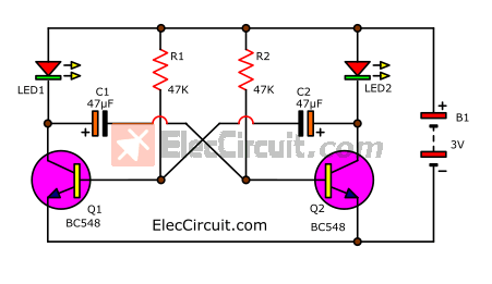
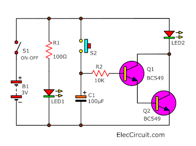
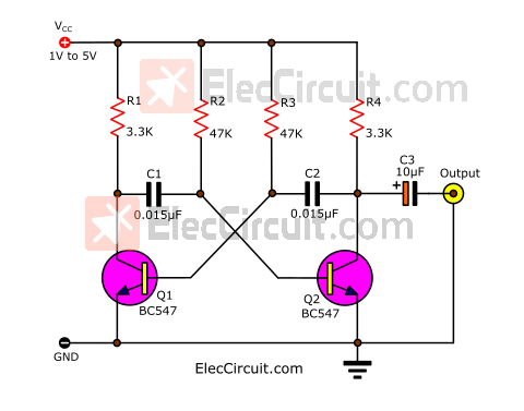
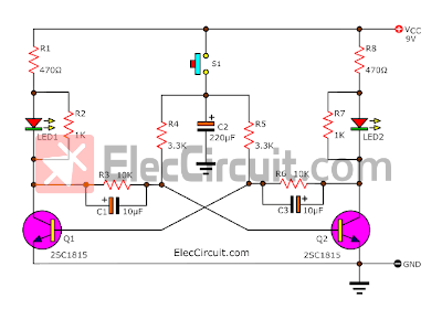
Two LED flasher circuits
This calls for more Free Running Multivibrator work to resemble Flip Flop, which encourages itself repeatedly. The Q1 and Q2 be Transistor PNP be usable general (2N3906,2N2907, etc.)
Learn more: LED blinking circuit using transistor
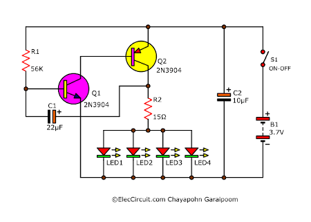
Flashing Bicycle LED Taillight Circuit
Using transistors instead of ICs because they are simple and economical. It is quite simple because there are few components. But learning its working principles is very interesting.
Read more: DIY bike light
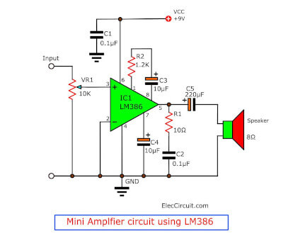
This is my first audio amplifier circuit. I use the LM386 as the main amplifier; it is a low-voltage (4V–12V) amplifier designed specifically for audio applications. Which can be used with a small 9V or 3.7V Li-ion battery operated with as little current as 5 mA and amplification up to 500 mW. It is enough to expand the sound from a mobile phone to a 3-inch loudspeaker easily.
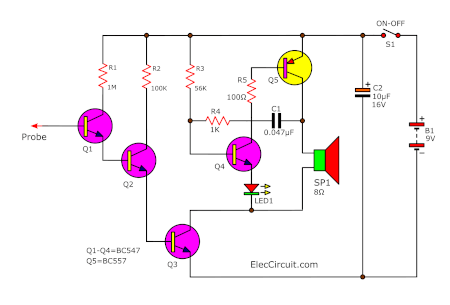
Non-Contact Voltage Tester circuit
Do you want a tool to check the AC main without touching it? This circuit can do it. In a simple way, in-circuit use transistors without IC. You can hear a sound, and show it with an LED display.
Let’s create a simple automatic solar light circuit or a Solar Night Light Circuit. My kids made it for daily use and to learn electronic circuits. They worked well, so we are happy.
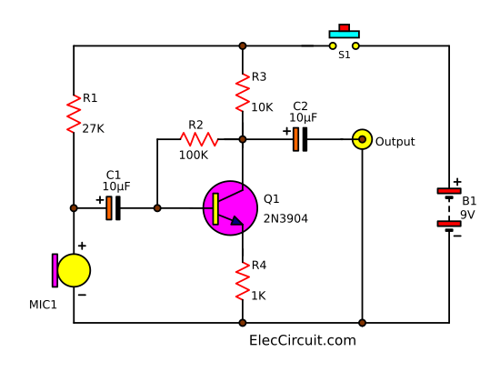
Simple Condenser Mic Preamplifier Circuit
The mic brings to change the sound into electrical signals. it is a basic circuit and uses a 9V battery
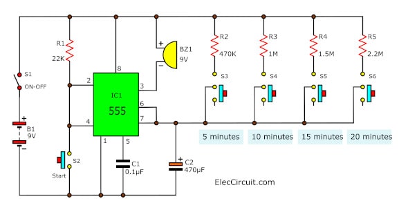
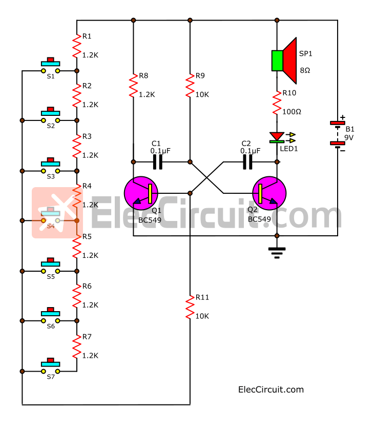
5-20 Minutes Timer using 555 timer
This timer circuit uses a 555 IC timer. It is small, compact, and portable. For the alarm by using the buzzer. We can select the time 5, 10, 15, and 20 minutes with S3 to S7 as the order. You can read more: 5-20 minutes 555 timer with PCB layout.
Gel cell battery charger circuit
It can charge any size of the Gel cell battery and extend the life of the Gel Cell battery. While the circuit is running, the LED indicates charging
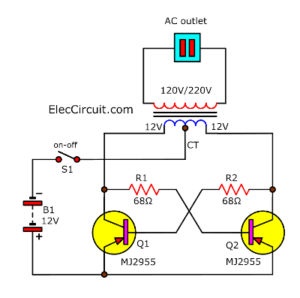
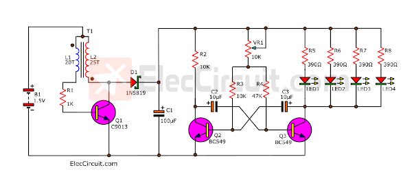
When you need to use a small light bulb with a 12V battery. But no light. Why? It requires an AC line of 220 volts. How do I convert 12 VDC to 220 VAC? There are many ideas for this. But we are in a hurry. Try this circuit, the simplest inverter, with just basic components, 2 power transistors, 2 resistors, and one transformer. So easy!
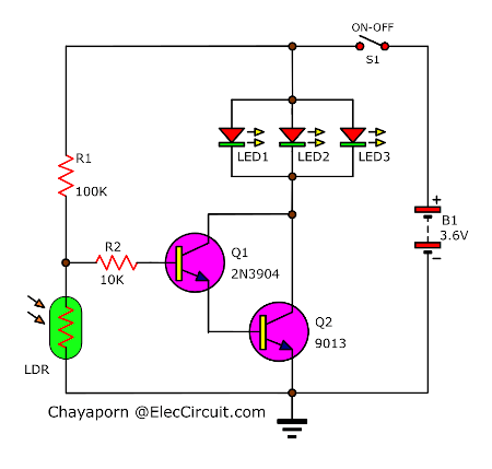
Automatic LED Night Light circuits
Try making a simple automatic LED flashlight with only 5 basic components. And, we would have learned about the transistor, LDR, LED, and more that work together as a voltage divider.
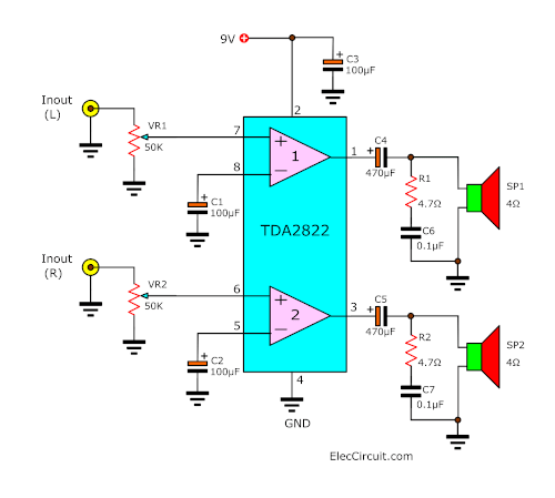
TDA2822 stereo amplifier circuit
Try making a simple automatic LED flashlight with only 5 basic components. And, we would have learned about the transistor, LDR, LED, and more that work together as a voltage divider.
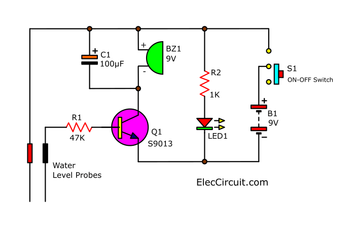
Simple Water Level Alarm Circuit using a Transistor
It worked by sounding an alarm when the water level rose to the set level. So we can close the water valve in time and prevent an overflow with only basic electronic components.
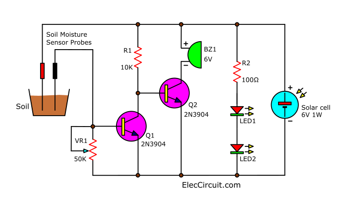
Solar-powered Plant watering alarm circuit
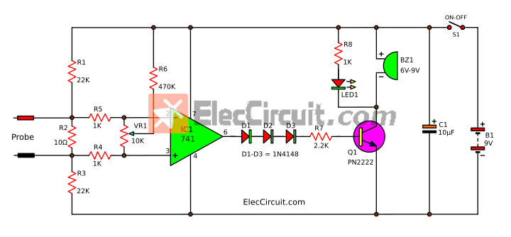
It will sound an alarm whenever the soil is dry. So, we can water the plant to prevent it from dying. The solar cell works like a 6V DC power supply to save us money by not requiring batteries. It can be built easily with a few parts (without IC).
30 min Transistor Timer Circuit
We can use these simple electronic circuits. To learn the basic timer circuit. The working of the circuit is based on learning the charge and discharge of the capacitor. And we can apply it to turn on-off electrical appliances. In the application, just put a relay instead of an LED.
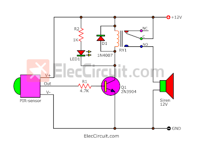
If you have your own private space and do not want someone to intrude, this motion detector alarm circuit will definitely reduce your worries.
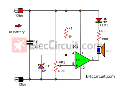
Continuity Tester Circuit with Buzzer and LED
This is a continuity tester circuit with a buzzer and LED. Also, I like this circuit. Because unnecessary to take my eyes off the tested circuit. We will hear the buzzer and see the LED glow. READ MORE
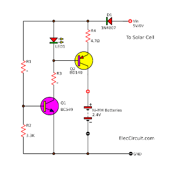
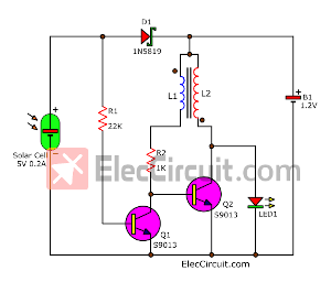
Simple 1.2V AA Ni-MH Battery Solar Charger circuits
Create it with common parts for charging 1.2V AA, So easy and cheaper. READ MORE
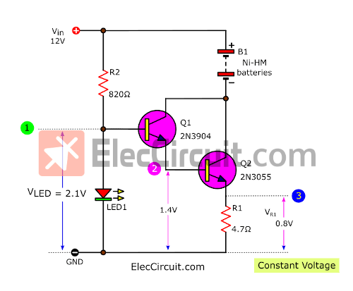
Constant current circuit using transistors
Learning experiments with a simple constant current circuits using transistors, and a few plain parts, was so helpful, especially the Ni-HM battery charger.
It’s efficient enough to last for 1 year. These circuits only use a few components consisting of two to three transistors, four resistors, and three capacitors.
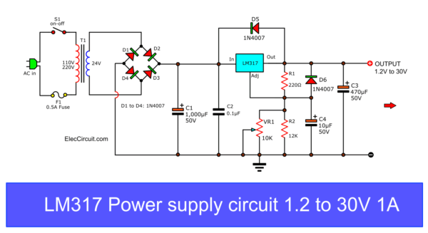
Sometimes you need a 1.5V power supply instead of a battery. Or other levels like 13V, 4.5V, 7.5V, etc. Use this variable-regulated power supply. Which is my first power supply. It has still worked well after 30 years.
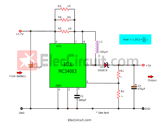
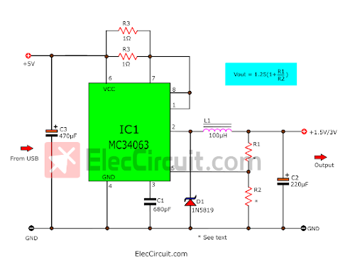
Here is a 3.7V to 5V boost converter or step-up switching circuit using MC34063 and a few parts,1N5819,100uH. For 200mA-300mA of load current.
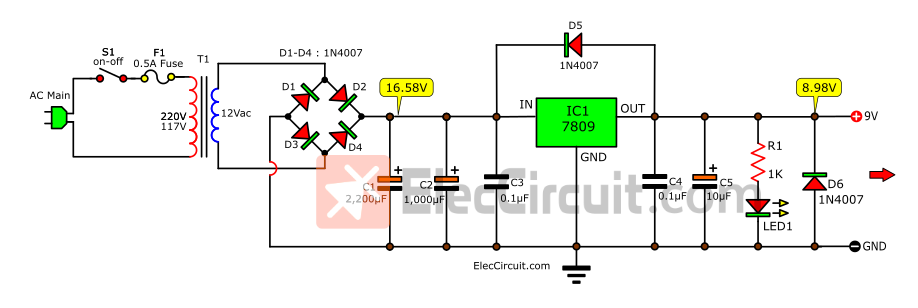
9V Regulator circuit using 7809
Let’s create a 9V regulated power supply circuit to replace a 9-volt battery. These circuits can deliver 10 times more current than a battery and saving us time and money to replace it when it dies.
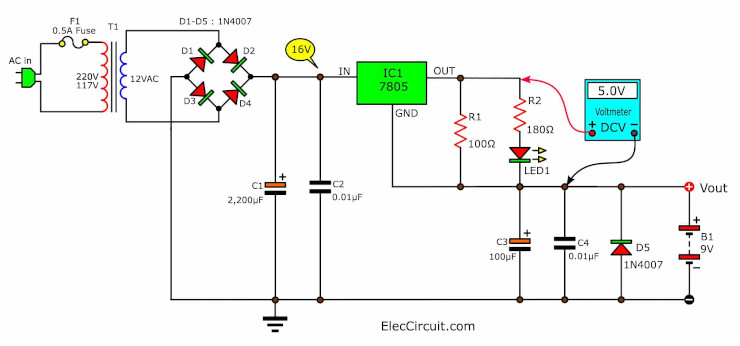
If you are looking for a 12V AC adapter. You can create it yourself even as a newbie. It can supply all circuits that require a 12V DC source under 2A. For example, the TDA2004 Audio Amplifier. Especially, it is built with a hammer!
Other electronic circuits for beginners
Here is a list of basic electronic circuits, which you can look at below.
Sound Generator, Oscillator
Toy Organ circuit using transistors
Let’s play with a simple toy organ circuit. A daughter of mine is interested in piano. But at the moment we are not ready to study it. Believe it or not, we can create a simple piano circuit by ourselves.
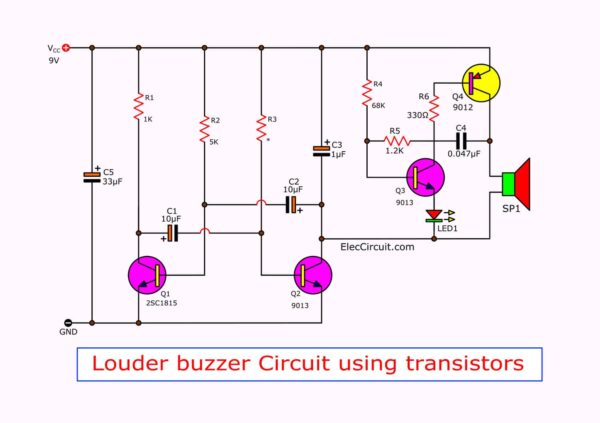
Let’s make the electronic buzzer circuit in simple ways. But useful and well worth it and the price is lower than 1$. By using just a 9-volt battery only.
It is easy to do that. They have 3 circuit ideas for you.
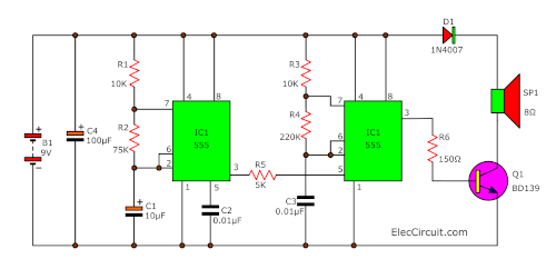
It can be a tool or accessory for repairing television or radio receivers, amplifiers, etc. It will produce a small-frequency signal. It uses a 1.5V battery power supply.
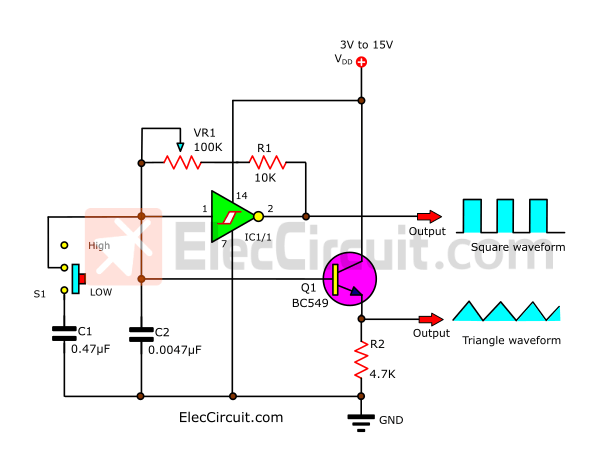
Triangle wave generator circuit using Schmitt-Trigger
It can create a Square or Triangle wave at the output with just a small number of electronic components. I made this a while back to learn about CMOS Gates and an Astable Multivibrator.
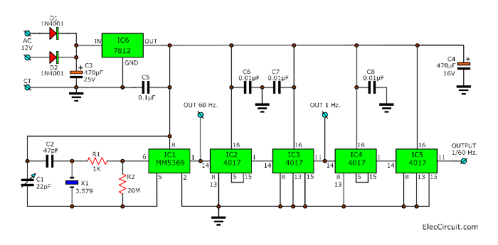
60 Hz Clock Generator Circuit using MM5369
It uses MM5369 and crystal as the main components. So, they can be used as a calibrator for standard frequency. They also give 1HZ, 1/60Hz, and 3.579MHz at TP.
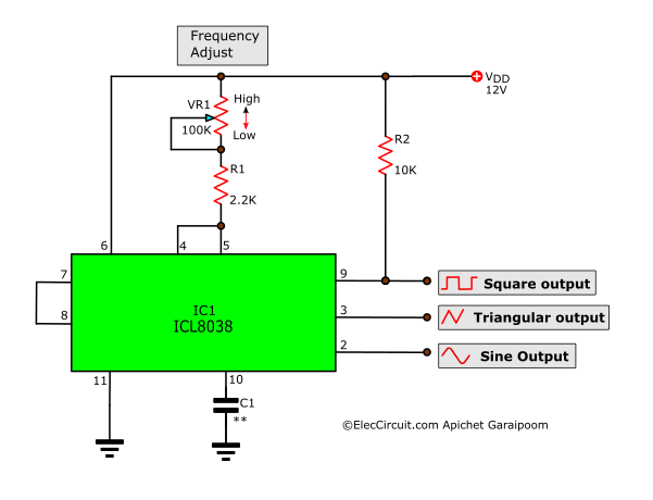
ICL8038 Function Generator circuits
If we need a function generator circuit. We have many ways to do it. Using the ICL8038 waveform generator is a great option. It is easy to use and inexpensive.
Lighting, LED circuits
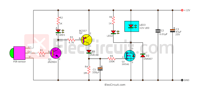
Simple Automatic Motion Sensor Light Circuit
Is there a way we could save as much electricity as possible?
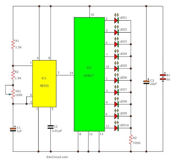
LED Chaser circuits using 4017 + 555
There are 5 circuits with PCBs for LED Chaser circuits or Running lights. They use CD4017 to drive LEDs and IC-555 as an oscillator pulse generator. It is best for a beginner or for kids to learn digital also my son loves them.
LED chaser circuit using transistors
Since my daughter has tried making the LED chaser using ICs (CD4017 and NE555), it has worked well. But recently, she has been learning how to use transistors.
Simple Coin Toss Game circuits diagram
It is a type of simple electronic game that simulates a real coin toss with LEDs. You could build it in your free time to play and enjoy with others.
Solar Cell
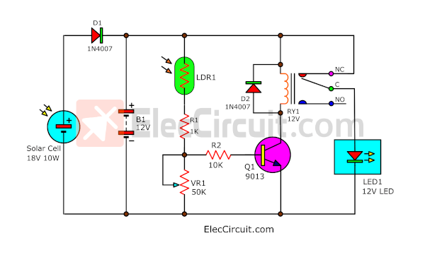
Outdoor 12V solar light circuits
If we need lighting around our home at night. But those areas are without an AC line because it is hard to do the wiring there. And we also want to save on electricity costs.
Agricultural circuit diagram
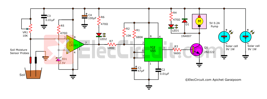
Automatic Plant Watering with a Solar Cell
Using a solar cell, a DC pump, a 555 timer, and an LM311 comparator. It worked well and was also very efficient, requiring only power from the solar cell rather than a battery.
Controller, Timer
The easiest way is to turn on the light only when needed and turn it off when not. But in practice, we often forget to turn off the lights even when they are not needed.
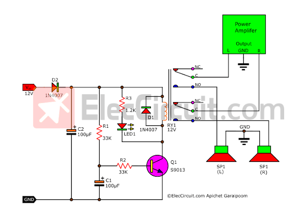
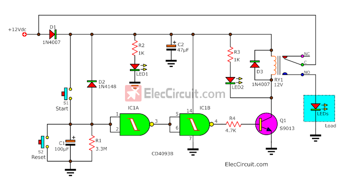
Simple Speaker Turn-on Delay Circuit
Every time you turn the OCL power amplifier on, within the first 3 S, you hear a loud “tlub” sound. It is annoying. Also, caused by a voltage spike that can damage the speaker. But this circuit can help us.
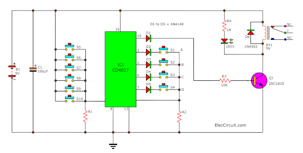
10 Key Code Lock Switch Circuit
We do not need to carry a load key and do not worry about your keys being lost. We just must remember to commit to code only.
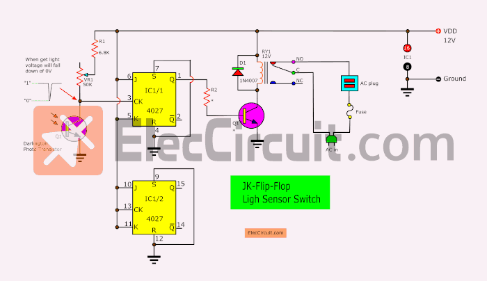
Digital Electronics Projects using Flip Flops
I am going to show you these Flip-Flop Switch Circuits. Imagine you can use your life is better with your own electronic project.
Meter, Tester, Detector
Battery Voltage Monitor circuits
When the voltage level is lower below 12.4V. To extend the lifespan of the battery, we should always bring it to be fully charged. The circuit will alert us.
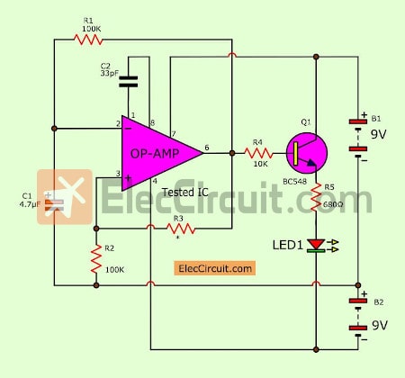
You can use them to fast-check the many op-amps IC good with blinking LED circuits. It has a few parts so cheap and easy to build.
Battery charger circuits
7805 Constant Current Battery Charger circuit
7805 has many helpful. One thing is we can use them as constant current regulation. It is so easy and more convenient than using transistor circuits.
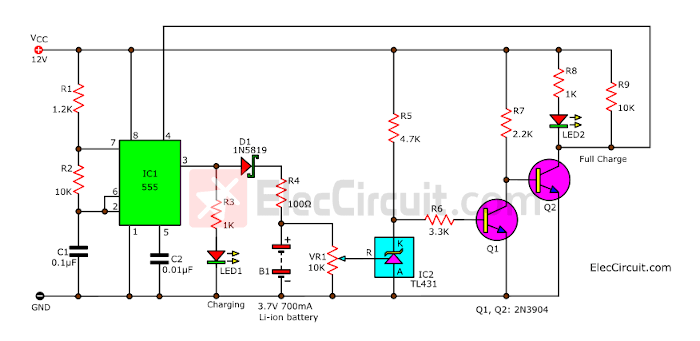
3.7V Li-ion Battery Charger Circuit
We made the circuit with commonly used components such as the NE555 timer and TL431 shunt regulator. It uses the principle of charging the battery with a low-current pulse signal. Making it a safe and impressionable performance charger.
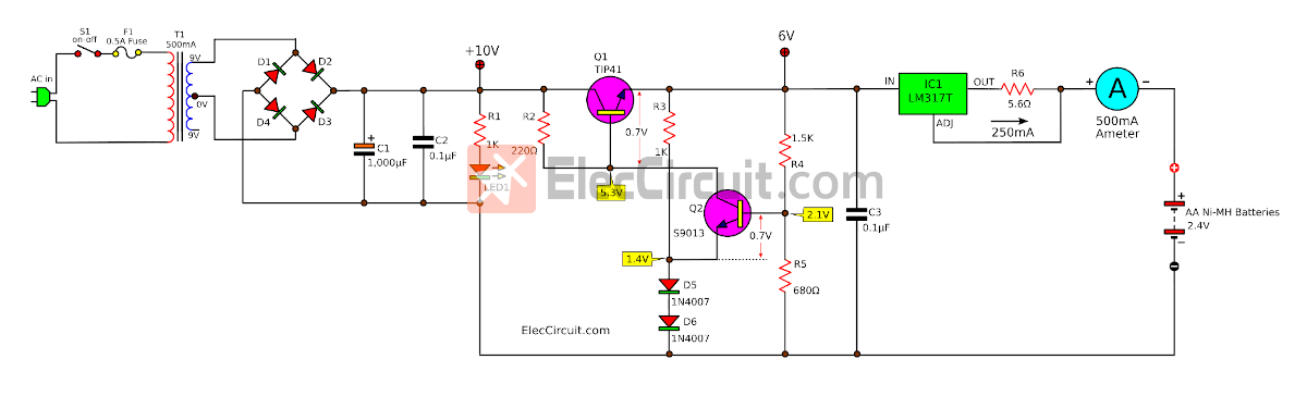
Here is a constant current and voltage AA Ni-MH battery charger circuit.
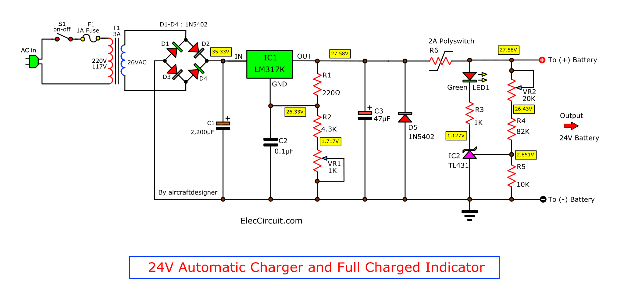
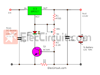
6V, 12V, 24V Lead acid battery charger using LM317
This lead-acid battery charger project is for 6V, 12V, and 24V batteries. Although there are many methods to choose from. But you may be missing If not read this post to the end.
DC converter, Switching mode
5V Low Dropout Regulator Circuit using transistor
The 6V input voltage can make the output regulator 5V 0.5A. So, the voltage across it is 1V only.
Read more: 5V transistor Low Dropout Regulator Circuit
USB 5V to 12V DC-DC Step-Up Converter circuit
This circuit will increase the voltage from 5V to 12V load without IC. It is good to learn a switching mode regulated power supply in low power output.
- 1.5V or 3V Step-up Switching regulator circuit
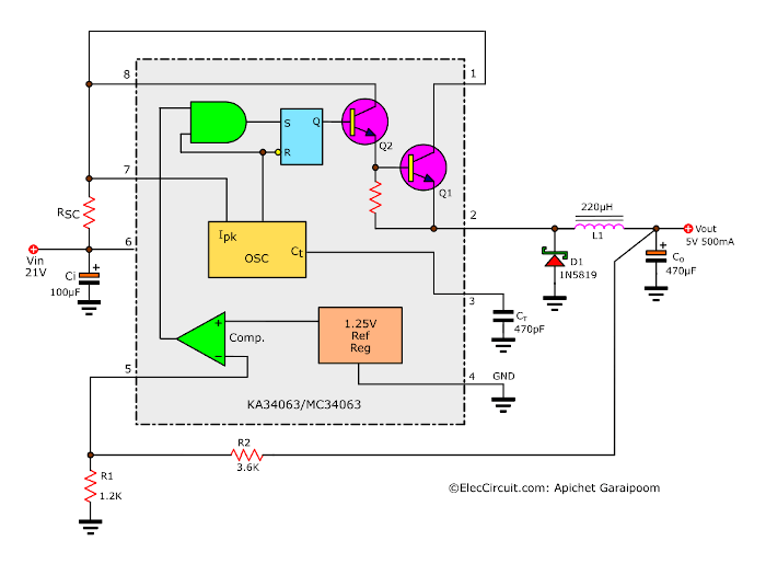
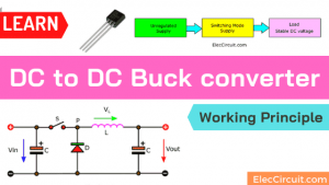
- 5V 2A Buck converter circuit using KA34063
- USB 5V to 12V DC-DC Step-Up Converter
- USB 5V to 1.5V/ 3V Step Down Converter
- 1.5V to 5V boost converter circuit
Basic Amplifiers
Conclusion
You will see that these circuits are simple, or in some cases, basic circuits, which can help solve our problems. We hope you get the most out of it and are able to improve it over time.
GET UPDATE VIA EMAIL
I always try to make Electronics Learning Easy.
Related Posts

I love electronics. I have been learning about them through creating simple electronic circuits or small projects. And now I am also having my children do the same. Nevertheless, I hope you found the experiences we shared on this site useful and fulfilling.
Hi
I don’t know much about electronic circuits and I would love to try, how can i tell the vaultage of the capacitors used?
If am to go buy the components from a radio shack?
Hi, Dee dave,
Thanks for your feedback.
Also, I do not know a lot of Electronics.
Every day, time is running so fast I need to take care of my children.
When I have free time I will learn electronics with make circuit and share it.
It is good ideas to learn capacitor. It is useful basic.
You should learn first, then you can know to buy. Because sometimes you can save with buy a few components for make a lot of projects. For example, You can use 1N4007 (1000V,1A) instead of many silicon diodes, 1N4001,1N4002 etc. They are the same prices. I hope you can understand my English is poor. Of course, I will try to improve it.
Can I get PCB for some of the project such as Video Amplifier,O-30 volt power supply
The simple projects of electronics students. we providing embedded system training in trichy for all steaming students.
Good site for coding. If I have free I will learn too.
can you design a circuit that can produce square wave ,saw tooth and sin wave and show me where the terminals of an oscilloscope and power supply are connect please
ecually i want a design of an oscilloscope
Hi Mziwenkosi,
Please see the function generator: https://www.eleccircuit.com/xr2206-function-generator/
Your idea is very interesting. If your project is successful. Do not forget to share with me, thank you.
How do I go about starting a design for an inverter that outputs 15kv ac?starting with the first segment of the design, what questions do I ask myself? How do I decide what values to give the components of each part of the design? Sort of a DC to DC to AC Coninvertor so to speak. Or am I just whishfull thinking? Either way how do I start giving values to the components to make a DC to DC Converter Work for a Set Voltage in mind, say 300kv? How do I set the first voltage divider and establish a working Vs?
Thank you,
Michael Cote’
Tl082 surround circuit
Hello Saravanan,
Do you want a surrounding circuit?
hello, sir nice and valuable information in your article. the diagram is very easy and easy to read and make.
sir, I want to know that in one of your diagrams like Learn 30 Minutes Transistor Timer you mention The Transistor value BC 549, I think this is an on/off switch transistor.
sir can use BC 547,548 for this circuit.
Hello raj,
Thanks for your feedback.
Yes, you can use BC547, BC548, and BC549 or BC550. They are small NPN transistors.
What kind of software do you use to generate those funky colorful schematics?
Hello Witek,
Thanks for your visit. I like your question.
Now I use the Inkscape software on Ubuntu OS.
Before, I used Illustrator on MAC and Corel draw on Windows OS.
Have a great day.
Thanks
I want to make 24V battery low voltage alarm circuit
Hello Ganesh Shinde,
Thanks for your visit to my site.
I am sorry. Now, I do not have a 24V battery low voltage alarm circuit.
But it is much interesting. I like this.
Unfortunately, I am busy. I would like to find/test this circuit for you.
I may use LM339 as the main. https://www.eleccircuit.com/lm339-quad-comparator-ic-datasheet/
But I will add a 12V regulated power supply for LM339. Because It should get 12V stable voltage.
Then, at the input, I will use the voltage divider circuit with 2 resistors and use a potentiometer to set sensitivity.
This is just an idea. But I cannot confirm it will work well.
Please think first to try it. Have fun.
thanks for this great work
Thanks for your feedback.
There are a few projects where you have added PCB artwork… would it be possible to get the PCB artwork in Gerber format, where we could get the board made by JLCPCB for only a couple of dollars
Nice explanation about the circuit with neat diagram.
Hello,
Thanks for your feedback. We will keep doing it. Thank you for your encouragement.