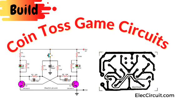
This is a simple coin toss game circuit with a time delay. It is a type of simple electronic game that simulates a real coin toss with LEDs. You could build it in your free time to play and enjoy with others.
The circuit has been improved from an old coin-toss circuit to make it more interesting and fun to play.
How does it work?
The circuit will delay the stopping of the LED’s blink, causing it to look more like the real thing.
The way to play is very simple; you just press the switch. Then, bolt LEDs will flash on-off alternately at high speed.
And when you release your hand from the switch, the LED will blink slowly. Until it stops at one of the LEDs. (It may be LED1 or LED2).
Each time we press the switch, the LED might stop at the same LED or another LED. So it is really similar to tossing a coin.
Read first for beginners: How do transistor circuits work
Simple Coin Toss Game circuit using transistor multivibrator
Let’s start with a simple circuit first. Many people like to use transistors because they are basic electronic components that are timeless. As a result, we incorporated them into this circuit. It can also help you learn the basics of transistor circuits with just 15 components.
How it works
This circuit is classified as a Multivibrator circuit. It is a simple circuit that most people are familiar with. The full explanation might make you bored. So, I would like to summarize only the important things.
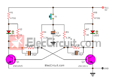
When we press a switch(S1), both transistors(Q1 and Q2) are biased correctly, and both capacitors(C1 and C3) will alternately charge and discharge.
Both LEDs will blink according to the transistors’ drive, ON-OFF(Light-Dark) alternately at high speed.
When we release the switch(S1).
Some current that still remains in the capacitor(C2) will then be discharged to supply the bias current to the base of both transistors. But the amount of current discharged will gradually decrease until it eventually runs out.
Thus, the frequency of both LEDs blinking will gradually decrease until it completely stops at the last moment. It will remain bright until we press the switch again.
We should use different colors for the LEDs, such as RED and GREEN.
Both resistors(R2 and R7) that are connected across the LEDs are to improve circuit stability.
Why?
While the voltage drop across the LED does not reach 1.7V. The LED does not conduct current according to its properties, so current will flow through the resistors instead.
The designer is really smart!
Those who want it to blink longer after the switch is released. This can be done by increasing the capacitor C2 to 330μF or 470μF as needed.
The power supply for this circuit is a typical 9V battery.
Parts list
0.25W Resistors, tolerance: 5%
R1, R8: 470Ω
R2, R7: 1K
R3, R6: 10K
R4, R5: 3.3K
Electrolytic Capacitors
C1,C3: 10µF 25V
C2: 220µF 25V
Semiconductors:
Q1, Q2: 2SC1815, 45V 0.1A, NPN TO-92 Transistor or equivalent
LED1, LED2:
S1: Normally Open Pushbutton Switch
9V power supply circuit
How to build
I built this circuit for fun with my daughter. And to learn about LED flashing with a transistor multivibrator circuit. So, we chose to assemble them on the breadboard. See below.
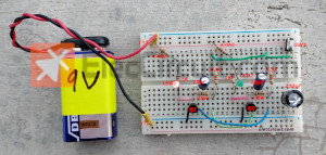
For those who want a more permanent circuit, maybe it is better to build on the perforated PCB. Because there are very few parts.
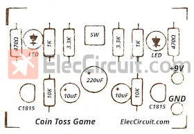
However, for those who want to keep it well organized, you can build it on a real PCB using this PCB layout.
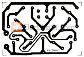
and Component layout below.
What is more? See another circuit!
Circuit ideas that you can get useful
Head Tails electronic Game using NE555 CD4017
This circuit uses integrated digital, NE555, and CD4017 with LED display easily. It takes more equipment, but I think it’s a good way to learn how to use digital circuits.
Principle of the circuit
When 9V voltage comes to the circuit C1 will charge through the VR1 and R1 fully.
IC1, R2, R3, and C2 are included as the astable multivibrator to generate square wave frequency. Then, send the signal from pin 3 of IC1 to the trigger.
Which uses the Time-on of the wave as a signal of the trigger, the pin 14 of IC2(Input pin).
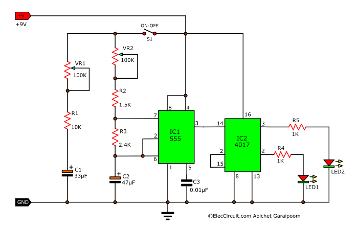
It causes the output to come out to pin 3, the LED1 glow but LED2 goes out.
When the signal comes to trigger pin 14 again, causing the output pin 2, the LED1 is On and LED2 is OFF.
Learn: How does NE555 timer circuit work
Both LEDs will turn on and off alternately.
When the signal comes to trigger at pin 14 again. It will restart. But since the astable multivibrator generates square wave high frequency, it seems that LED1 and LED2 are always on.
But when S1 is open circuit ( we release S1) causing C1 to discharged out through R1, VR1, VR2, R2, R3 and C1, and C2 until completely discharged, causing the astable multivibrator circuit to stop. So we see that either LED glow (maybe LED1 or LED2)
Note: Each before playing, we should adjust VR1 to adjust the discharge time of C1 or adjust VR2 to adjust the frequency of the square waves. If VR1 is not adjusted, the result of LED1 and LED2 will be the same every time.
Here is the circuit that you may like it:
Download This Post
All full-size images and PDFs of this post are in this Ebook below. Please support me. 🙂
Related Posts
GET UPDATE VIA EMAIL
I always try to make Electronics Learning Easy.
Related Posts


I love electronics. I have been learning about them through creating simple electronic circuits or small projects. And now I am also having my children do the same. Nevertheless, I hope you found the experiences we shared on this site useful and fulfilling.
Hi how are you both, I have missed your circuits lately and look forward to them. Paul. UK
Nice design using transistors instead of IC”S BRAVO!!!
Thanks my friend, for your feedback. I am glad you like it.
Years ago a magazine had an article on building a “rudimentary” computer. It was based on the old game of “21”, with 21 lamps, a “player” button and a “machine button. Each player, (and the machine) taking turns, could light 1, 2, or 3 lamps, with the object of the game to not to be the one forced to light the last or 21st lamp. It used a stepping relay. The machine would invariably win! It worked on the principle that there are 5 groups of 4 within the number 21, with one left over. If the player lit 1, the machine would light 3, if the player lit 2, the machine would light 2, and so on. Whatever number the player would choose, the machine would light whatever was needed to add up to 4. It would seem that with modern components (LED’s, controllers, etc.) such a game could be constructed easily. Would you, or someone you know be interested in such a project?
Hello, uncle.
Thank you for visiting our website.
Uncle’s question is very interesting. But right now my father is not free.
Because my dad was busy teaching me to learn about transistors, which I was quite slow at learning.
But in the future, I will learn more until I can answer your uncle’s questions.
We will inform uncle via email again.
Very sorry once again.
May God bless you uncle. 🙂