So what are we going to learn about electronics today? Since a while back, we have experimented with using a transistor as a switch, which is very useful.
Now what about using that knowledge to create a simple water level alarm circuit using a transistor?
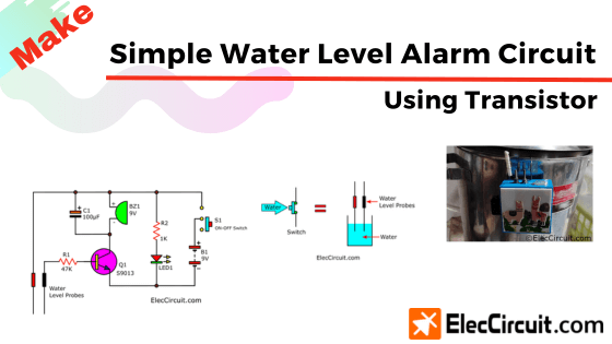
It worked by sounding an alarm when the water level rose to the set level. So we can close the water valve in time and prevent an overflow.
How it works
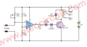
First, let’s start with this simple transistor circuit. Its purpose is to drive a buzzer (BZ1). When S1 closes, it will let a small base current flow through R1 to the B of Q1. This forward biasing allows a much larger current to flow through to BZ1(buzzer).
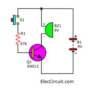
Learn: The transistor works as a switch
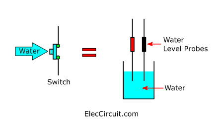
As you may already know, water is conductive. So instead of a switch (S1), we use two wires to probe the water, which may also be known as the water level probes. Suppose the water level increases and touches the two probes. The water will conduct the current between the probes, like a closed switch.
Now we try assembling it on the breadboard, which is quite easy because there are not many components. Next, let’s understand this circuit.
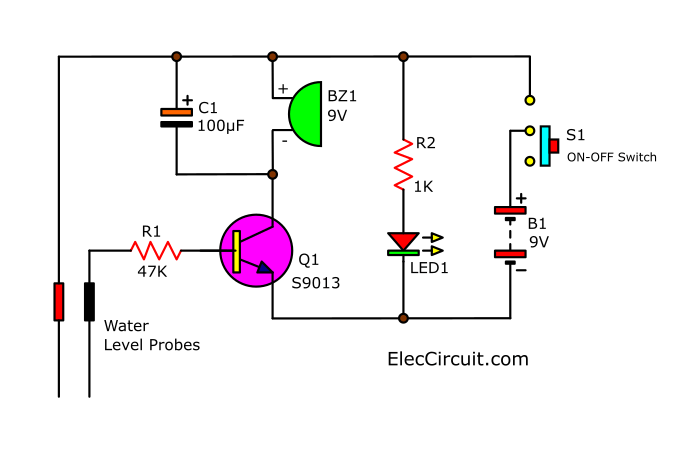
Start with the S1 switch to on, letting the current flow through R2 and LED1. Causing the LED1 to light up, which shows that the circuit is operational.
See other simple electronic circuits
Understanding through the phase diagram
For easier understanding, we will remove C1, S1, R2, and LED1 for now. Which resulted in the simplified diagram below.
Water level below probes
So if the water level is lower than the probes, (1) it can be compared to an open switch cutting off the current.
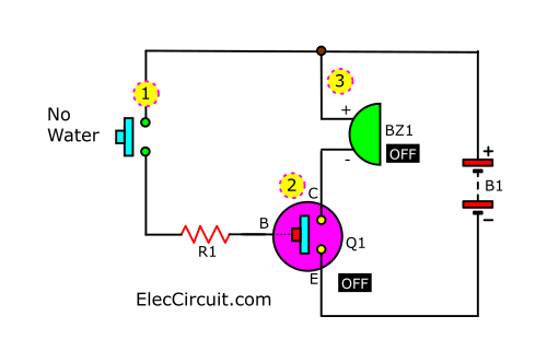
(2) Thus, there would not be any base current flowing to B of Q1. This means that the Q1 isn’t working yet, and right now, it is just acting like an open switch. (3) Because of that, BZ1 does not receive any current and remains off.
Water level reaching probes
When the water level rises to the point of touching the two probes, just like a closed switch, (1) they will conduct current through the water. Allowing the base current from B1 will flow through R1 to bias Q1, turning it on. (2) And now, between C and E of Q1, it is connected just like a closed switch. Letting the current flow through BZ1, causing it to buzz.
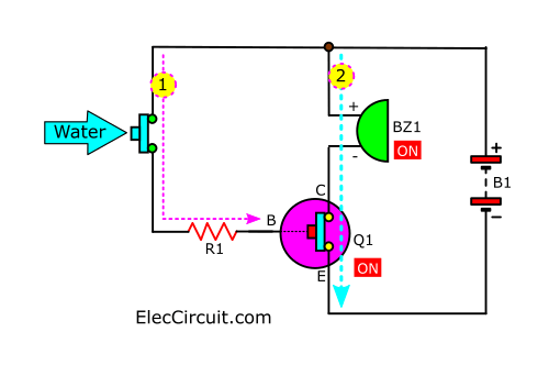
Note: The C1 increases the stability of BZ1 to work better.
We use this idea for make : Soil moisture detector circuits and automatic controller
The components list
Q1: S9013, 0.8A 45V NPN transistor
C1: 100uF 25V, Electrolytic capacitor
R1: 47K, 0.25watts resistors
R2: 1K, 0.25watts resistors
BZ1: 9-volt buzzer
B1: 9V battery
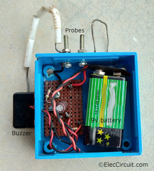
The wiring, Perforated board,
Recommended: How does a SCR thyristor work?
How to build
My children have built this circuit twice already, each time using the same circuit but with different usages. The first was for a fish tank, and the next was for a drinking water tank.
Both times, the circuit is assembled on the perforated PCB with a wire for off-board components.
From my experience, the water level probes themselves should be made of stainless steel so that they will not rust. If we use a normal non-rechargeable 9V battery, it will be enough for around 6 months. So instead, we should use a 9V Ni-HM battery because it can be recharged and reused.
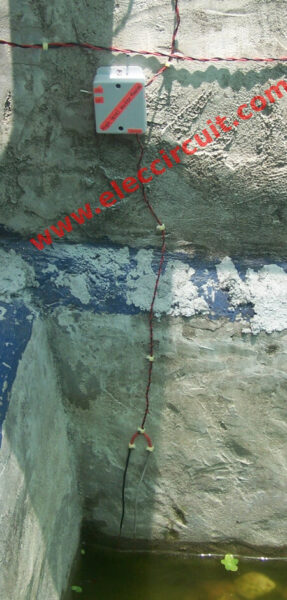
Fish pond version
My son made this circuit and installed it in a cement fish pond. So we would not overfill it during the time of the refilling.
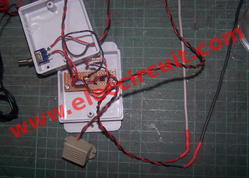
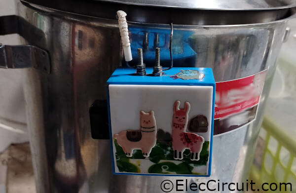
We use a small electrical box, big enough to fit all components, and then manage the wires neatly. As for probes, we use the main wires here.
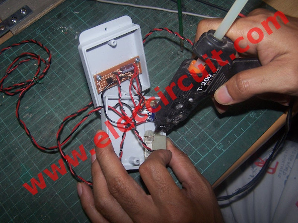
Use hot glue to glue the buzzer and LED1 to the box.
Then we test this project as the video below.
Water Level Alarm installed in a fish pond
Water tank version
Recently, my daughter built this circuit as well, but this time it is for a drinking water tank.
Conclusion
This circuit is created in the simplest way possible, with the goal of learning the basics of a transistor as a switch. But maybe, in the future, we might add an automatic valve control instead of an alarm.
You may like this: Automatic water level controller circuits
Download This
All full-size images and PDFs of this post are in this Ebook below. Please support me. 🙂
GET UPDATE VIA EMAIL
I always try to make Electronics Learning Easy.
Related Posts


I love electronics. I have been learning about them through creating simple electronic circuits or small projects. And now I am also having my children do the same. Nevertheless, I hope you found the experiences we shared on this site useful and fulfilling.
its better that u should be try to made a complete water controlling system
if ur tank become full ur water pump will automatically off
n when ur tank will be empty the water pump will automatically ‘on’
thanks for your circuits.