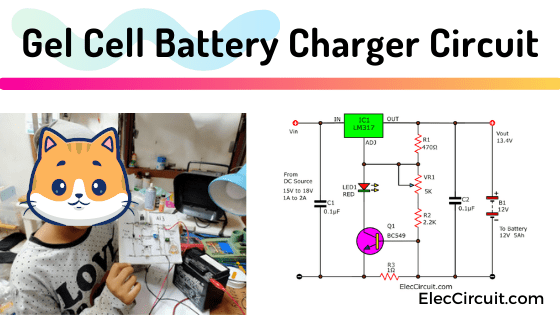
I love gel cell batteries because of their maintenance-free and low cost. But sure, we would need a suitable battery charger circuit for a longer lifespan. Let’s take a look at this gel cell battery charger circuit using LM317.
Why did I recommend this particular circuit? Because of its low voltage charging, merely 13.4 volts. As a result, it generates next to no heat.
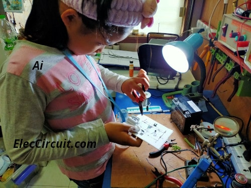
Moreover, it is easy to put together. My ten-year-old daughter managed to build it. That means you can as well.
And, we can charge any Gel cell batteries with a charging current, of 300mA, 650mA, and 1.3A.
While charging, the LED will light up, indicating the charging process. When the battery voltage rises to a certain level—in this case, 13.4V—the current flow will reduce to almost zero milliamps.
This minimum current flows into the battery at a similar rate to the battery’s self-discharge. Consequently, it prevents electrical discharge and over-changing. The LED will also turn off in the process.
What is a Gel Cell battery?
Some of you may still not know them. Let’s get to know it a little bit.
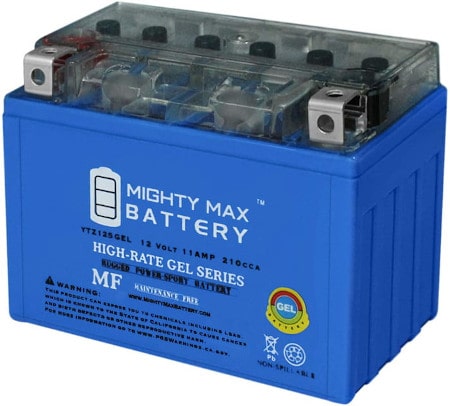
Cr: Photo from Amazon Mighty Max Battery
It is a type of valve-regulated lead-acid battery or VRLA battery. This gel cell battery doesn’t need much maintenance and is safer to handle when leakage occurs due to the gel-like electrolyte. The gel battery also slowed the electrolyte evaporation, extending the battery lifespan. Some may call them dry-cell batteries.
Note that some batteries use lead-calcium-silver as a grid instead of lead-antimony or lead-calcium. Which will require a higher charge voltage. But since I rarely find one, this charger will only take account of a normally found gel battery.
We do not have to see the inside. Just use it is well enough.
Cheaper gel battery sources
I love gel batteries. And I use them in many kinds of projects. Because it is cheap and can easily be found at a mechanical store near us. Most of the time, I’ll get it for 0.6 $ a piece from a motorcycle repair shop.
Most modern motorcycles use these batteries. The common sizes are 12V 2.5Ah, and 5Ah. They are usually replaced after one year of operation. They can, however, still be used in small electronic works that use less electricity and often put less strain on the batteries than they were intended.
When it really expires, it can still be sold for recycling as well. Better than some other types of batteries that are only used once and then discarded.
Gel cell battery charger circuit working
In the circuit below, we are using the LM317 as a 1.5A Adjustable Positive Voltage Regulator. It will convert the sometimes rough and unstable DC input voltage into a stable voltage to charge the battery.
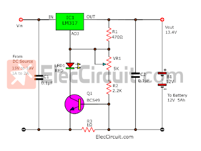
We manually adjust the 5K VR1 Potentiometer until the output is 13.4V.
The current is determined by the R3 current limiting resistor on the ground (Negative Terminal).
You can choose the R3 value from below to match your preferred charging current.
- 300mA = 2.2Ω, 1 watts
- 500mA = 1Ω, 1 watts
- 1,300mA = 0.47Ω, 1 watts
At this point, some people (including my daughter) may not understand the concept of a battery charging system.
I always believe that explaining with pictures will make it easier to understand. So let’s take a look at the block diagram below.
First operating: High charging current!
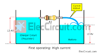
We compare the charging circuit and the battery to two water tanks. They both have different water levels (voltage levels). The charger circuit is set to 13.4V but the battery is still at 12.8V.
Then we connect both tanks together via the water pipe (R3 Resistor) to pass the water (electricity) from the charger circuit’s tank to the battery’s tank.
Water naturally flows from a higher place to a lower place, which is the same as electricity. It will start to flow from the charging circuit into the battery.
Recommended: Recycle Free Li-ion battery from E-waste
The greater the water difference, the stronger the current will flow. But within the limits of the size of the pipe itself, in this case, it is 600mA, according to the 1Ω resistor that we’ve chosen.
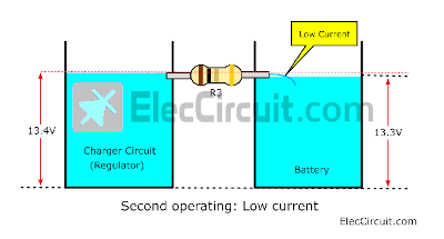
Then, the water continued to flow through the pipe until the water level in both tanks reached almost the same level.
As the block diagram above shows, It looks like the battery voltage continues to increase. But when it got closer to 13.4V, the charging current began to decrease to almost 0A.
Now let’s get back to our real circuit again.
When the current flows through R4, this will result in a voltage across the Base and Emitter of the Q1 Transistor being forward-biased. Thus, Q1 starts to conduct current to LED1 and adj of IC1.
The red LED1 will indicate the battery is being charged. When the battery voltage reaches a certain level, the current will drop to a few milliamps, lowering the voltage across Q1 and LED1 in the process.
When the current drops to about 5%, the LED1 will turn off, and the current will drop further until it almost reaches zero.
See: Automatic battery charger circuit
The AC adapter
We use an AC adapter as a power source for this. As the circuit above, the plug pack 500mA DC for a charging current of 300mA. The current AC adapter should be more than 1,500mA at 15V to 18V.
- 300mA output requires the plug pack 500mA up.
- 500mA output requires the plug pack 650mA up.
- 1,300mA output requires the plug pack 1,500mA up.
For 1,300mA: If possible using the 2000mA (2A) current is most suitable.
What is an AC adapter?
If you are a beginner, sometimes you may confuse the circuit inside it.
When you cannot buy the AC adapter use can build an unregulated power supply from parts that you have. It will save you money.
How to build it
My daughter wants to create this project. By she assembled all the equipment on cardboard. Then connect those devices with copper wire. According to the circuit above. In this way, it makes this project look easier.
IMPORTANT: Be careful to insert the correct polarity device. Such as LM317, LED, transistor. Otherwise, the circuit will definitely malfunction. Quick Learn before make
LED1: If the wrong polarity is inserted, it will turn off.
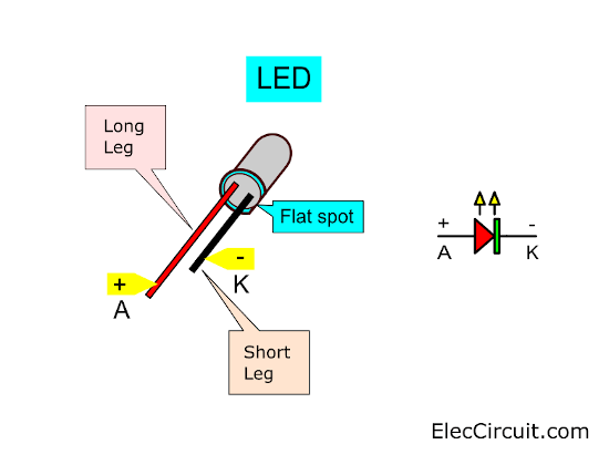
Note: Only a 3mm red LED should be used. Because when working, it will be clearly visible and the current flowing through it is very little.
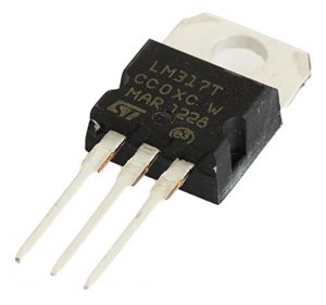
LM317: Don’t put the wrong polarity at all. It may suddenly overheat and become damaged. Its metal body is connected to the output pin. We should be very careful. It short-circuited into other parts.
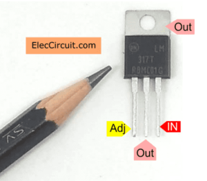
Note: While in use, it becomes warm. To prolong its service life. We should also install the heatsink on it.
Transistor: It should fit it correctly as well. It has three legs, be careful!
We may use equivalent transistors: BC547, BC548, BC549, BC550, etc.
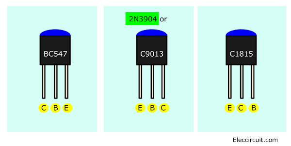
Look at the above, You may use other small NPN transistors, too. But different leg positions be careful!
But most importantly, it should be a transistor with high gain (100 hFE up) or a good quality transistor. Otherwise, it won’t be able to conduct current well enough to drive LED1 bright up.
Potentiometer: You might confuse its legs. At least my daughter is one of them.
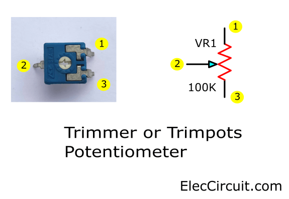
See above, It is 100K. But in this circuit 5K. It is an example.
Parts you will need
IC1: LM317, 1.5A Adjustable Positive Voltage Regulator
C1,C2: 0.1μF 50V, Ceramic capacitors
R1: 470Ω, 0.25W Resistor
R2: 2.2K, 0.25W Resistor
VR1: 5K, potentiometer
R3: 1Ω, 1 watts Resistor
LED1: Red LED 3mm
Q1: BC549, 0.45A 40V NPN transistor
Heatsink
Note: Very important, friends should choose a good quality LM317.
Check out the LM317 on Amazon
How to setting and usage
When we finish the circuit and checked everything already. Then, apply the power supply to Vin, DC 17V at 1.5A. Without connecting the battery. Next, adjust VR1 until the Vout is 13.4V.
After that, connect the 12V battery to the output. The voltage level will drop. When measuring the current flowing through the battery initially it is approximately 600mA.
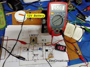
Notice that the LM317 gets hot. Because there is a lot of current flowing through it and the voltage drop across it is high.
When the voltage level starts to rise, close to 13.4V. The current through the battery will also be less. It takes about 10 hours. It shows that the battery is fully charged. Because the voltage level is exactly 13.4V.
Notice that the LM317 doesn’t get hot at all. Even I used to charge it for 24 hours. The circuit works normally. And the battery doesn’t get hot too, maintaining the battery voltage very well.
Not only that I like to keep old circuit ideas. It is maybe useful for you. See below:
Keep reading:
5 Lead-acid battery charging circuits
Download This Post
All full-size images and PDFs of this post are in this Ebook below. Please support me. 🙂

Related Posts
GET UPDATE VIA EMAIL
I always try to make Electronics Learning Easy.
Related Posts

I love electronics. I have been learning about them through creating simple electronic circuits or small projects. And now I am also having my children do the same. Nevertheless, I hope you found the experiences we shared on this site useful and fulfilling.
Handy Dandy Circuit using our old Friend The LM317T
Hi Mr OHM 1970,
How are you?
Yes, Though very ancient, they still have many uses.
I am looking for a simple schematic for a 12volt 5Amp gel battery. I however, want to charge it all year around for emergency use with a possible low amp such as 0.2amp or lower is better. I will put it in my attic just for emergency alarm. It will support an alarm that it has only one SCR and one resister of 15k that I had already made.
I need help of the 12volt low amp charger.
Thank
is this charger having an auto cut off ? when the charged battery is full
Hi isagani quinto,
No, but it pretty safe for battery. Because low current and constant voltage.
Keep reading: https://www.eleccircuit.com/automatic-battery-charger-circuit/
nop, its always on, its put the battery on “float”
I make the circuit , it charges the battery, le transistor limit the current of the circuit, so, the charger always work , but if the battery its very low limits the maximun current, it charger slowly, in general a practical circuit
Hi, Jose Aguilar
Thanks for your feedback.
Realy, the red Wire from the DC adapter to ground????
Hello Ralf,
Thanks for your visit to my site.
You are great. I just updated this to clearly see.
Thanks again.
thank your cct
Hello THUSHARA,
Thanks for your feedback.
Muito bom o projeto….
Hi, Zelino
obrigada
Very interesting circuit but I would like it charge a 20Amp so I need to boost the current.
I’m thinking of putting a 3055 as shunt transistor across the 317 with maybe a driver transistor for the 3055.
Would this work?
Hi Nemo,
Do you mean a 200Ah battery? Yes, It is charged with 20A of current. You may use 2N3055 in parallel to boost the current up.
I also want to try it. But I do not have a battery and transformer. It is a great idea to do!
Have a fun day with electronics.
Great circuit but the red LED doesn’t light. Any ideas why, please?
Hi,
Thank you very much for your question. We are glad that you found the circuit useful for you.
From my experience the LED glows very dimly when the battery voltage is lower than 12.4 Volts.
And most importantly, we use red LED size 3 mm. It consumes very little power.
We can confirm that this circuit works fine more than 2 years.
But it charges a small current. My dad is coming up with a circuit that can charge a large battery, and cut off the power automatically.
Once finished we will notify you via email. Thank you for following again. 🙂