These are the 1.5V LED flasher circuit. They require a low voltage of just one AA 1.2V/1.5V battery, it’s efficient enough to last for 1 year. And these circuits only use a few components consisting of two-three transistors, four resistors, and three capacitors only.
So, It makes this circuit easy to put together and cheap.
About decades ago, making the LED flasher was quite easy. Because it uses LM3909 with one resistor and one capacitor to get it to work. Also, it requires a low voltage of 1.5V to function.
However, this chip is not selling anymore, because the factory discontinued it.
But worry not, this presenting circuit is also easy. At least, we would not have a problem finding the components. Believe it or not, even 71 years old elderly can do it!
How does 1.5V LED Flasher work
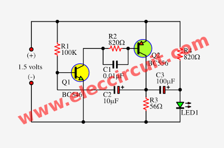
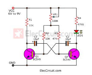
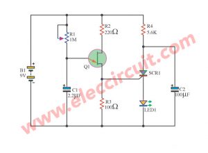
The circuit below is a 1.5V LED flasher that uses two types of transistors, NPN and PNP. Both can generate an oscillator that can make LEDs flash by using a voltage of only 1.5V. And also use a low current of 2mA only.
The components list
0.25W metal/carbon film Resistors, tolerance: 5%
- R1: 100K
- R2, R4: 820Ω
- R3: 56Ω
Semiconductors:
- Q1: BC546, 45V 100mA NPN Transistor or Equivalent
- Q2: BC556, 45V 100mA PNP Transistor or Equivalent
- LED1: 3mm LED, any color you wish
Capacitors
- C1: 0.01µF 50V Polyester
- C2: 10µF 25V Electrolytic
- C3: 100µF 25V Electrolytic
Read also: DIY Flashing Bicycle LED Taillight Circuit
How to build and testing
This circuit is very simple you can assemble it on a Perforated board or breadboard like me.
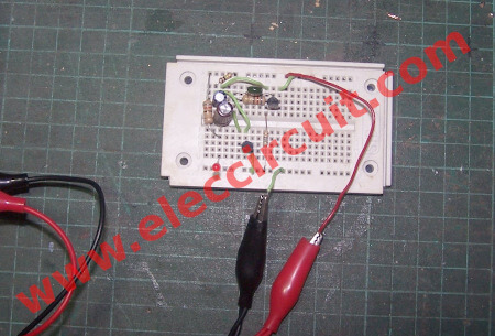
Then, I test it with an Adjustable DC power supply as video below. Normally LED does not glow with a 1.5V power supply. It will glow up when the voltage exceeds 1.8V. But with this circuit, we make LED flashes with 1.2V voltage equal to a general AA Ni-MH battery.
I notice they will flash faster when their lower voltage supply. So, we can adapt it as alarm low voltage batteries or other projects as you have ideas.
Meet 1.5V 4 LED Flasher Circuit
Our friend Andy wants a 1.5-volt LED flasher circuit. It can drive 4 to 5 LEDs with a speed controller. By still using the transistor circuit as the main component without an IC.
It is quite difficult if we use the same idea as above. Since our loads (LEDs) require too much current. We even tried modifying the components but could not do it.
God wants us to always develop and start with what we easily have.
Let’s experiment with a simple flashing light circuit again.
First, convert the idea from above into a more easy block diagram.
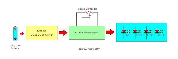
Right Block
We want every LED to be as bright as it can be. So choose to connect them in parallel, and there will be more of the current combined.
Middle Block
We will make the LED blink with the Astable Multivibrator circuit using a transistor.
Left Block
But the LED blinking circuit requires a voltage level of about 6V to 9V. This is not possible with a 1.5-volt battery. We need the step-up DC-to-DC converter to step up the voltage.
Turning it into circuit diagram
Next, we have to come up with the circuit according to the block diagram above.
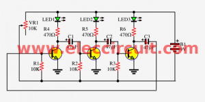
Astable Multivibrator Block
Circuit ideas that you can get useful
In this block, we experimented with a simple LED blinking circuit. Since we are already familiar with the two LED flasher circuits, I won’t repeat them again. for fear that this article will be too long (you might get sleepy).
But now we have reduced it to just one LED. Additionally, we added VR1 to control the flashing speed of LED1 from very slow, about 1 time per second, to 10 times per second.
Then we tried adding four LEDs in parallel. The circuit still works fine. But the flashing rate is slightly different. Because the current quantity changes. However, we can adjust VR1 to the desired flashing rate again.
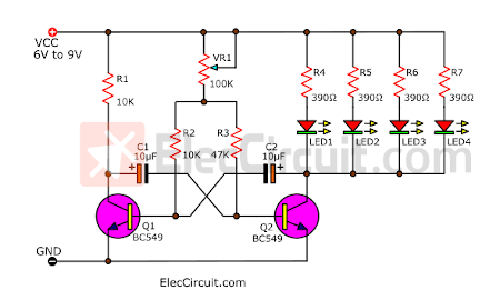
Other components that affect the flashing rate are C1 and C2. As its capacitance increases, the LED blinks slower.
When we reduce the capacitance of C2 to 1µF. It makes the LED’s lit time shorter. It is a good result, allowing the circuit to use less current.
Step-up DC to DC converter
Simply put, we need a circuit that changes the voltage 1.5V to 6V DC. The simplest method or circuit is a simple unregulated flyback circuit. Or Joule thief circuit.
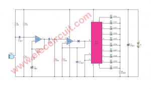
There are only 5 basic components, see the circuit diagram below.
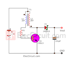
The principle is simple: Q1, R1, and T1 work together to be a higher-frequency oscillator generator circuit. The waveform at pin C of Q1 has a higher amplitude than the input DC voltage (1.5V). The D1 will only pass through the positive waveform and C1 works like a water tank. to store high water levels. Make the water level always high or always High DC voltage constant.
If we don’t connect the load, we measured the output voltage about a maximum of 30V. Although, it applied with only a 1.5V battery. It is amazing. Of course, we also have to reload. So the pressure level is reduced.
In the experiment, there are three points of interest.
D1
Shouldn’t use the 1N4007 diode. But better use the 1N5819, 40V, 1A Schottky Barrier Diode. Because it works well at high frequencies. The voltage level comes out consistently high.
C1
The capacitance should be between 100µF to 470µF. I tried using 1000µF but it didn’t affect the load, so it was better to use 100uF.
Q1
Do not use transistors 2N3904, BC549, or 2SC1815 because their IC values are low, around 100mA. You should use transistors with IC values higher than 200mA because our load uses around 100mA.
The hFE should not be lower than 100, which I think uses transistors. Number 2N2222 or BD139 also work well.
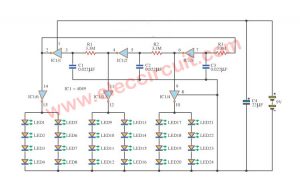
Next, we take each part and assemble them together into a complete circuit.
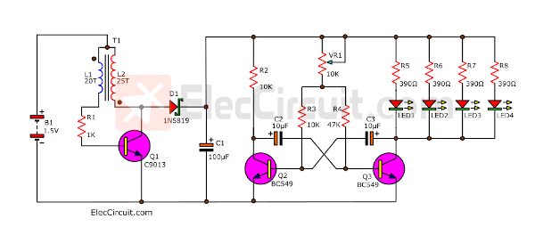
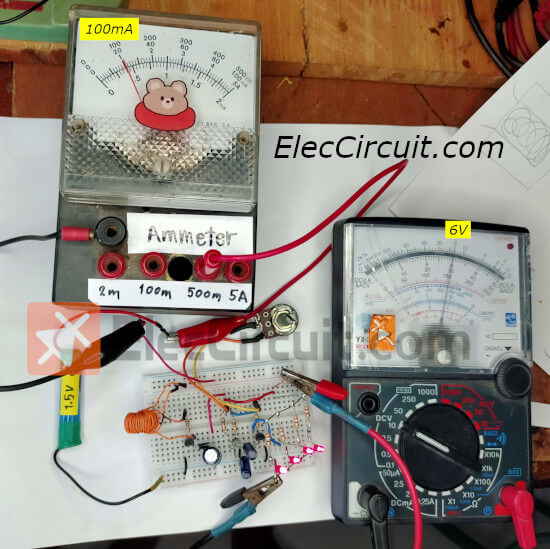
My daughter assembles this circuit on the breadboard as in the layout below.
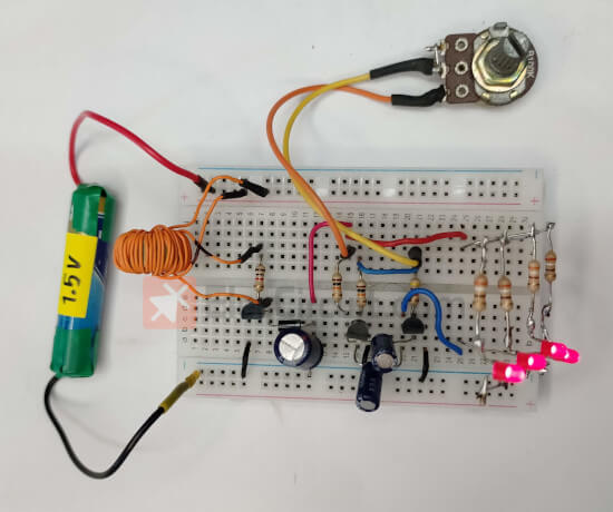
Then, she measures the current of this circuit at the input. It can be read as 100mA. And measure the voltage across C1 or VCC of the astable multivibrator. It can be read as 6V.
We can make a 1.5v led flasher circuit using transistors in this way. However, it requires the input current to increase as the number of LEDs increases. In the future, we may try to make a 1.5V LED blinking circuit using an IC for a smaller size and lower power consumption.
Here are three circuits similar to the circuit above.
- Electronic siren circuit with two transistor.
- A lamp flasher circuit using transistors
- Simple 1.5V LED Torch Circuit
Get This
All full-size images and PDFs of this post are in this Ebook below. Please support me. 🙂

GET UPDATE VIA EMAIL
I always try to make Electronics Learning Easy.
Related Posts

I love electronics. I have been learning about them through creating simple electronic circuits or small projects. And now I am also having my children do the same. Nevertheless, I hope you found the experiences we shared on this site useful and fulfilling.
hey the updates encouraging do you have electronic troubleshooting tips? thanks
how can i adjust duty cycle in this circuit
Great Circuit
The LM3909 was a Fun Chip To use…Too bad it’a Gone!!!
There are different rules out there, but these will be the most frequent ones you’ll come across.
Bro good day for 1.5 Volts power I want to put 4 or 5 PCs LEDs with speed controller. are the resistor, capacitor & transistors replaced? If so, what is the value for each of the components needed ? Thank you in advance
Hello Today I help my father to test 4 LED flashing circuit using 1.5V battery. It works very well. Soon we will post wait a minute. 🙂
Grato pelas iniciativas cidadãs.
Thank you for supporting I and my dad. I and my dad will concentrate continuously on making articles. 🙂
It interesting but how make T1?
Hi John
Please look at this: https://www.eleccircuit.com/mini-emergency-light-circuit/#Select_the_primary_component_first
At T1 is same this one.
Hope it can help you. 🙂
It’s a very good circuit. What is the minimum voltage applied to this circuit?
Hi,
Thank you. You mean this circuit right? I’ve tried it for a minimum voltage of 0.9V.
Have fun with this circuit. 🙂
It works fine. But the battery runs out quickly. T1 was an issue for me at first. I’ve made a mistake. grateful.
It’s okay not a big deal. 🙂