Here is an LM317 Adjustable power supply circuit. If you are a beginner in electronics. You want a good variable power supply. This may be the best project for you.
It can supply the output voltage 1.2V to 30V at the max current of 1.5A.
New update Please read below this article.
Variable power supply using LM317, 1.2V to 30V at 1A
This is the first DC power supply in my life that made to use in many projects. It is ideal for those who want to adjust voltage from 1.25V to 30V and currents up to 1A.
Which is sufficient for normal use. For example, It is a power supply instead of a one 1.5V AA battery.
When you want to listen to music from a 30 watts amplifier that required a voltage of 24V 1A, it can be done easily.
Before we commonly used the transistor regulator that is very difficult, large, and probably more expensive ICs.
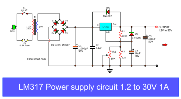
LM317 Power Supply Circuit diagram
But this circuit can be created with a single IC lm317 based variable power supply.
The LM317 or LM117 series of adjustable 3-terminal positive voltage regulators is capable of supplying in excess of 1.5A over a 1.2V to the 37V output range,
And has many special features that I like are :
- Output Voltage Tolerance 1%
- Line Regulation 0.01%
- Load Regulation 0.3%
- Prevent the deposition temperature.
- Short-circuit protection.
- Ripple is eliminated with a ratio of 80dB
- Maximum input voltage 40V
Recommended How to use the LM317 circuit in many ways. We like to see you grow.
How it works
Followed circuits below.
Here is the step by step process:
First, the transformer T1 is changed an AC 220V down as AC 24V to the bridge diode rectifier D1(1N4001) to D4(1N4001).
There is DC voltage into the filter capacitor C1 equal to DC35V.
The output voltage from IC1 Depending on the Voltage Adj pin of the IC, or to adjust the VR1.
The VR1 is controlled the output DC voltage 1.25V to 30V (32V) or 37V maximum voltage at 1.5A max all range.
Note: If you want to start at zero volts (0V) Look Here
Let’s set output voltage with:
Calculate the LM317 output voltage
And we can calculate output voltage equal to:
Vout = 1.25 x {1+ (Rp/R1)
- Vref = 1.25V
- Typically R1 is 220Ω or 240Ω as a datasheet. I use the 220Ω.
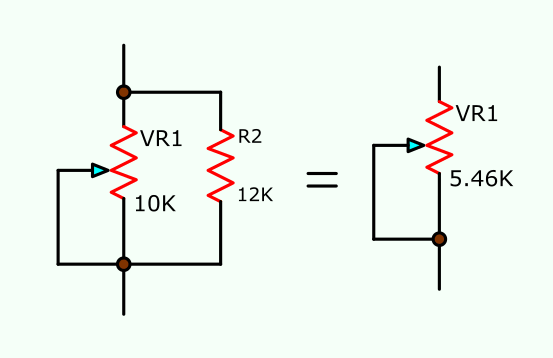
- Normally as a datasheet, I see them use VR= 5K (Potentiometer) But I have VR-10K only since it is easy to use.Rp = {(VR1 x R2) / (VR1 + R2)}
Then we test it, Suppose, rotate VR1 to the lowest resistance cause Rp = 0Ω. put it in the formula above:
Vout = 1.25 x {1+(0/220)}
= 1.25V
But, when adjusting VR1 to a maximum resistance of VR1 and R2 are parallel together.
Rp = 5.46K = 5460Ω.
Test it in formula above:
Vout = 1.25 x {1+(5460/220)}
= 32.2V
Then the capacitor C3 is Better performance filter of IC1.
The diode D5 and D6 ( both is 1N4007) is the protector from external voltage to reverse to makes the damage to the IC1.
Also: LM338 Adjustable Power Supply 5A and 10A
How it builds
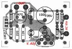
Then, We will assemble all the equipment onto the PCB. See the PCB layout and component layout and full content.
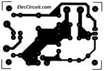
Actual-size of Single-sided Copper PCB layout
Fine voltage adjusting
Many begin friends tell me this project difficult to adjust voltage output. so I add potentiometer 1K and parallel 1K-resistor together. then connects them to VR1 as Figure below.
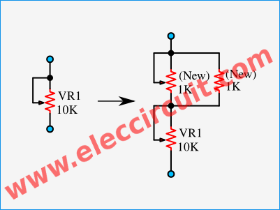
You will see that we can adjust the voltage at VR2 (new) is 4volts since the resistance sum of 500Ω approximately.
For example, I set voltage is 9V with rotate VR1 is 8.00V and rotate VR2 easily to control the output voltage of 9.00V.
View in the video below
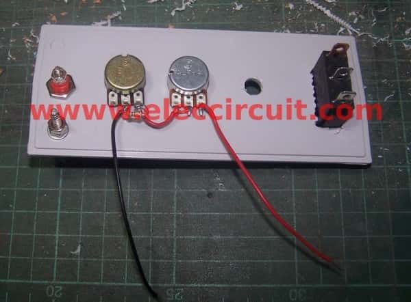
I assemble in the universal box to use easily.
Apply the transformer
I have old a transformer 12V CT 12V output. It should have a total voltage of 24V.
But I measure it as 30.9V too much voltage. It may cause overvoltage DCV as 30.9V x 1.414 = 43.7V.
Which can be damaged to IC1 by too much current.
The maximum input voltage for LM317 is 40V max. It can run well with 3V to 40V of input.
So I modify another transformer 12V CT 12V and 0V 6V 9V 12V output into 21-volts.
as Figure below
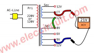
This circuit perfectly works, as in the video below. I can adjust the voltage output is 1.25V to 27V since I use the 21V output transformer.
If you can adjust 24V or 12V CT 12V. It causes output up to 30V. But IC overheats when a short circuit or overload.
I test the circuit with the 12V 8W lamp as a load. A steady (DC) Voltage will not be transferred from 12V.
Add LED Voltmeter display
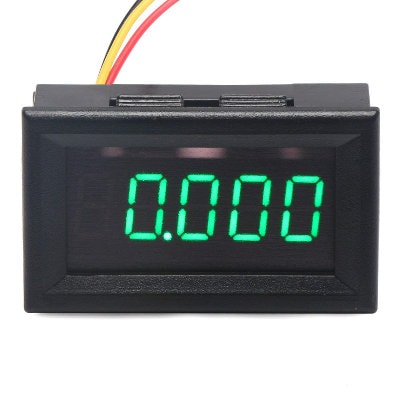
We can add an LED voltmeter to show a voltage level of output.
Mr. Ali Mohammed, ask me how to use 3 wires voltmeter, red, black, and yellow.
It is a good idea. It’s accurate and more convenient.
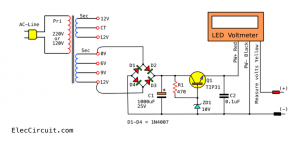
Block diagram of adding a voltmeter to the first power supply
In the circuit diagram, it needs an external DC power supply. We have to build a 9V DC regulator for it.
Please read this idea: Diy digital voltmeter panel meter
We connect a bridge diode (D1 through D4) to SEC (0 and 12V) of a transformer. Then we connect the measure voltage wire in yellow (+) to the output LM317 power supply. And Ground to (-).
Just this we can already read voltage output.
If you use other AC voltage such as 24 volts. You must change:
- C1 = 1,000uF 50V Electrolytic capacitor
- R1 = 1K 0.5W resistor
This so saves and easy circuit.
Why does it not work and FAQ
- C2 — you can use a 0.1μF electrolytic capacitor instead of 0.1uF 63V or 50V ceramic or mylar type. But we need to be careful to be correct lead.
- Transformer size—You should use 2A transformer to full current up to the 1.5A output. However, 1A transformer also works well lower current.
- WVDC All capacitors, You can use a voltage of 50V. Specifically, Electrolytic capacitor!
- Why R1 is coal?—If Diode-D5 is the wrong terminal. It causes an input high voltage across LM317. Then, it comes to R1 to VR1 and R2 to ground. So, They get high current and burned.
Please check all diode terminals in the right way only.
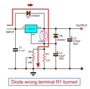
- If you put the D6 polarity incorrect, The VR10K will burn.
- You can solder the components on Perforated or universal PCB Board.
- Why use C3-470uF? It is a filter capacitor. You can use a 1uF tantalum capacitor the same in the datasheet. But I use this because I have it. It also works well.
- Why is the output 1.5A?—The current is not constant at 1.5A throughout all voltage ranges.
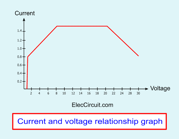
If you need high current more. Please look at:
LM317 2N3055 high current regulator.
- Electronic devices with polarity Must be put correctly. For example, Diodes, Electrolytic capacitors, LM317, etc.
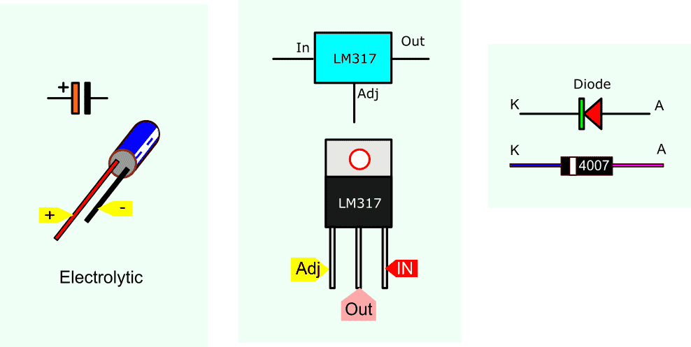
Use an LM317 as 0 to 30V adjustable regulator
There are many ways to do 0 to a 30V adjustable regulator. But this is easiest with helping with two diodes.
When the current flows the diodes. It always has a voltage across it of 0.65V to 0.7V.
If we connect the two diodes in series. They have 1.3V across them. In normal LM317, start voltage at 1.2V. But this voltage is in both diodes. So, the output starts at 0V.
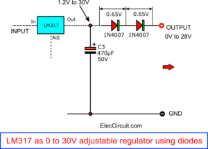
But it has a disadvantage. The current is slightly reduced by the resistance in diodes
Download This
All full-size images of this post are in this Ebook: Elec Circuit vol. 1 below. Please support me. 🙂
Sample circuit of LM317 power supply Others
Besides this circuit, We also have other interesting circuits. Choose a simple first.
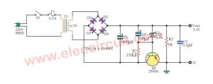
LM317 adjustable voltage regulator 1.2V to 10V
This is also LM317 based variable power supply and low noise, adjustable voltage output: 1.25V to 10VDC (0-12V) from 12V battery source, so simple circuit
If you have a 12V battery. But you have a load to use the voltage 1.5V to 10V at 0.75A. You should reduce the noise as well.
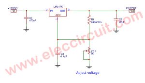
In this circuit, it will converter DC low voltage, 12V to be out of 1.25V to 10VDC. by can give current topmost get about 1.5A.
You should use an IC number LM317K(on TO-03). Because it has powered more than LM317T (on TO-220).
While it works. It is so hot too. So, need a heat sink that is large-sized.
Others parts function
- The R4 used to adjust the output voltage level.
- The C1-470uF 25V (electrolytic capacitors) act like a miniature battery that supplies power during the spike.
- C3-0.1uF 63V (Ceramic Capacitor or Mylar Capacitor) reduces noise
- C2-22uF 25V to decrease all noise well. The other detail, Read in the circuit.
Simplest LM317 Adjustment power supply, 1.25-15V
This is the simplest LM317 based variable power supply. We can adjust the output voltage of 1.25V to 15V. The output current level of each voltage is different.
For example: If you adjust the voltage of 12V, the current level will be 0.5A. When you set the voltage of 15V, it causes the output current of 0.2A.
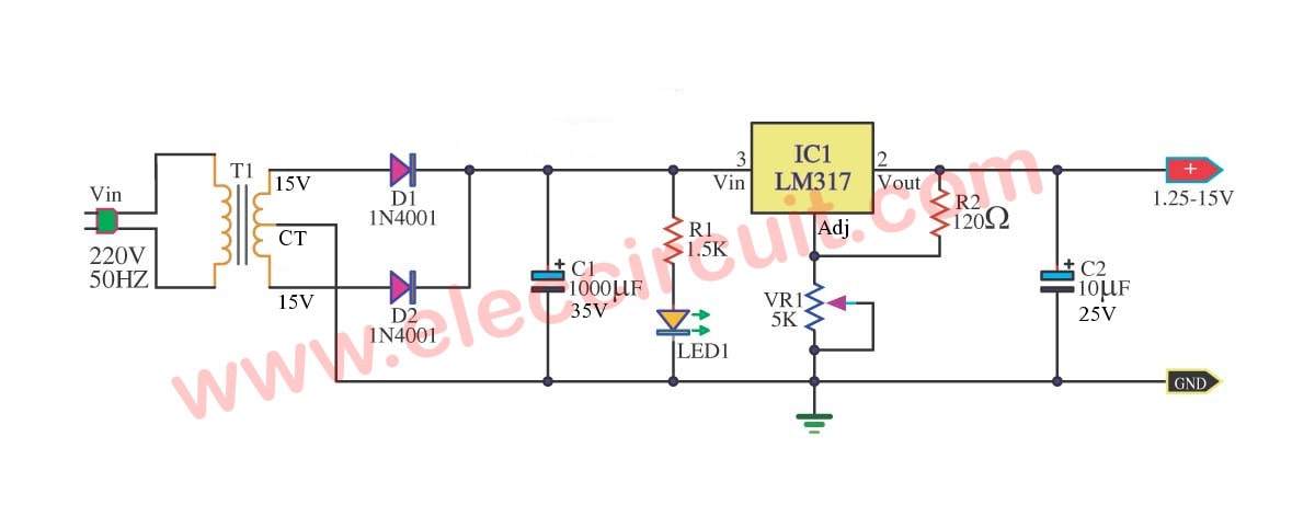
Simplest LM317 Adjustment power supply, 1.25-15V
In the circuit diagram, When the voltage from 220V AC main reach transformer. It reduces voltage AC220V into 18VAC.
Then, this low AC voltage flows to a full-wave rectifier, D1, D2.
Next, DC voltage flows into C1. It is a filter capacitor to smooth and increase the DC voltage of 20V as an unregulated voltage.
After that, the unregulated voltage flows to the DC Regulator circuit. Which uses an LM317, R1, and VR1.
This circuit provides a constant voltage to the load. Which we can adjust many voltage levels of 1.2V to 15V by adjusting VR1.
By the way, C2 is a 0.1μF capacitor to filter out the transient noise which can be induced into the supply by stray magnetic fields.
More great LM317 Power supply circuits
In addition, You maybe not like this. But you may modify these circuits to work well too. Below.
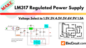
- DC Linear selector Regulator— derivers 1.5V, 3V, 4.5V, 5V, 6V, 9V at 1.5A. It’s easy for the selects voltage output.
- 0-60V DC Dual Variable supply Using LM317&LM337, Max adjusts the voltage of 0-60V. It’s high volt and starts voltage at zero! good job.
- Best Adjustable DC power supply 3A; —1.2V-20V, 3V-6V-9V-12V High current for all circuit easy to use.
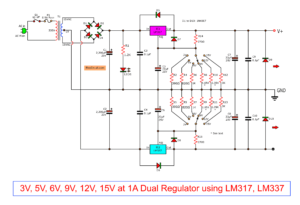
- Dual power supply 3V,5V,6V,9V,12,15V—using LM317, LM337. There positive and negative voltage outputs for all circuit easy to use.
And now you can see
3A Adjustable Regulators using LM350T

I love electronics. I have been learning about them through creating simple electronic circuits or small projects. And now I am also having my children do the same. Nevertheless, I hope you found the experiences we shared on this site useful and fulfilling.
(My first Variable DC Power Supply 1.2V to 30V 1A by LM317) R1 was be coal. 🙁 I wonder why?
Yes same prob Admin! and made much coal, i guess atleast a full truck load of R1 coal. R1 is attached from Vout to Adj of LM317.
Thank you @electro.
(My first Variable DC Power Supply 1.2V to 30V 1A by LM317)
does this really work? because i had a hard time in doing it successfully. the one that i built doesn’t work. 🙁 my output doesn’t have an output of 30v and the 10k potentiometer i can’t figure out how to work it properly. please help me.
P.S. my diode is always buring up. 🙁 please help.
help.. the output is correct but when i connect it to a desired circuit it will low the voltage.. why?????? 🙁
very nice projects for learner thanx a lot sir
Hello, slyles
This projects is works, please see others:
https://www.eleccircuit.com/lm317-linear-power-supply-regulator-selector-15v3v45v5v6v9v-15a/
We use LM317 on a lot of project :https://www.eleccircuit.com/tag/lm317/
Hi everyone..
This is madhav..
Recently i bought an ac-dc power adaptor in which i have an option to vary my output from 1.5v to 12v.
But when i adjust the knob to 4.5v and check the output using digital multimeter the out put is varying by 3-4volts..
say for 1.5v it gives 3.6v or somehthing..
Is this correct reading??? so that on giving load it will show exact reading..
just tell me whether the problem is with my device or with m y understanding????????????
The transformer based variable power adapters output voltage will not be exactly what’s printed as it’s the rms voltage that is 3 Volt means 3×1.41 = 4.2 volts or so.
is the output of this is adjustable from 0-30volts?
admin can i use 0.1uf 50V electrolytic capacitor insteda of 0.1uf 63V polyester. because im having a hard time finding that capacitor.
Dear sir.
I have copied your schematic and drawn out the pcb i have located all the parts on the pcb except one which you show directly below the 10k pot. i have checked and rechecked the schematic and the pcb all to no avail i can not trace this item what ever it is. Sir would you be so kind and explain it to me. thank you in return. Rob
Dear admin,
May I ask if I can actually build this circuit in a universal PCB?
what will I use in transformer, 1A or 2A? thank you Sir.
can I use 2A 24V transformer??
i m not gettting output voltage ….is circuit digaram ok??…..i have tried many times
what if… instead of 24 v..i use 30 volts???
i mean if less or more than 24 V is used then ???
How do you calculate output voltage ???
How to calculate the heatsink size (length and width) according to load current and voltage drop meaning the power dissipation ?
Hi, Hitman
Please see in text.
@styles, all diode normally works.
@maine, You can use it but be careful about polarity electrolytic capacitors.
@Rob, The pcb is correct but you can use universal PCB it cheaper and faster.
I just finished my first 1.24 to 15V dc power with 2 LM317 voltage regulators but every time I connect my transformer (AC) its producing a smoke on the rectify area . When I use A Dc voltage supply it works fine …can’t figure out the problem. here is the schematic
admin bhai……how the potentiometer being connected in proj.
Hi, rahul
I solder potentiometer on PCB and Figure the components layout.
The LM317 will shutdown if more than 1.5amp is passed through it.
It seems a number of people leaving messages of failure to their project are missing this vital safety feature of the LM317.
Pin 1,2,3 Adjust,,, Vout,,, Vin,,,One Tiny Error Can Screw Up This Whole Circuit,,,Please Be Careful Everyone!!! This Circuit Works For Me!!! Thanks admin
What if I need to supply power from 3-25 V using the same structure here? How can I start with a minimum of 3 V output? I tried using zener diodes but they do not function as desired.
Also how is ripple voltage calculated ?
Pls sir help out, i built an amp with TDA2030, but it hums, what could be the reason? It happens to all TDA circuit I hv ever build, I use filter cap of 6800uf still it hums
how can i use this circuit for gettin pure dc of 0-10 volt which will vary according to variation in input 0-230 volt ac ??
that good projet……
because that application……….
any project in case all dc project have most of in 30v…….
thanks….
I just want to know which on of the 217 and 337 transistors outputs has a negative voltage and a positive voltage. Would be appreciated
sorry 337
when i connect it to a 24 v car battery it is overheating and suddenly shut down.
Hi, Kegan.
Thank for your feedback.
You can use LM337 negative dc regulator replace with LM317 IC. But you change voltage polarity to negative way.
In next time I will assemble them because I have more many ICs-LM337.
Hi, Vince
You can use this circuit to 24V car battery source.
Please you check the circuit again some part may not correct.
I have made this circuit, its working perfectly.
I’ve used 15V 1A transformer as input, 100ohm and 10Kohm resistors for 220ohm and 12K resistors respectively. Used both 10K and 1K pots as per the circuit. I am getting 12V dc output. I have also installed a Digital panel voltmeter to the circuit. Its working fine.
Thank you Admin, for posting this article.
The project works very good but without the VR 10k…….whenever I connect it and turn the circuit on it starts to burn.
please I need help because I want it a variable power supply
Hi, Kumar
Thanks for feedback.
Hi,Karim.
Thanks for your feedback.
I am sorry for your project do not work.
Please check wiring parts again.
In particular,Diode-1N4002 at between Output and ADJ of IC1.
If you switched lead of diode in wrong polarity.
It may will cause too much current flow through it to VR-10k with too much current until the potentiometer burned.
Hi,Kegan
Thanks for your feedback.
Please wait me in the future I will show you the project that use LM337 in main parts.
Hi admin
i make this circuit i used all 1n4007 diode & 24 v 1.5amp transformer but R1 get burnout & also 10k pot also plz tell me what is poblem
Hi,Ashok.
I am sorry you that your project not work.
Please circuit again.
Diode-1N4007 across IC1- IN and OUT lead. It may have problem or position of lead not correct. It cause high current flow through it to R1 and VR1 to ground.
Which make they are burned.
sir i chk those connection but problem is still thr plz help me
@ Ashok
I think IC1, D-1N007 may be damaged. cause too much current to R1 and VR1.
But you can test the circuit by follows step below.
1.no load.
2.remove VR1 and D5,D6 before.
3. Hold the voltmeter at output.
4.Then short between ADJ and Ground.
5. Apply AC-power line
6. If OK the voltage output must be 1.25V
and R1 not overheat.
Some times D5,D6 may error. Please check them again.
Goodluck.
Sir
which type of Variable resistor is used for adjusting voltage, as i used it when i move these it burns so it have any amperage for control? as per your instruction i will do it after printing PCB board.
in your above comment in 3 point you said hold voltmeter at output & GND right and ADJ is directly connected to GND that is remove R2? What about R1? I used C2 electrolytic Capacitor as you said polyster?
Hi,Ashok
I think IC1, D-1N007 may be damaged. so test circuit as above.
In testing we don’t adjust voltage output.
We check IC1.
You remove VR1 then short ADJ and Ground of circuit by may be use wire jumper.
So you don’t need remove R2 because resistance across it is zero now.
if the circuit is normal it will be 1.25V at output.
But R2 burned again indicate that voltage too high which IC1 and D5 are damaged.
Therefore You check lead of any parts in correct only.
For example D5,IC1 and more.
C2 isn’t prblem you can use any type.
Please slowly check.
how to select transformer using KVA ratings.
if i want 230V 50Hz ac to down convert it into 24V ac.
hello admin ,,
can u please give a information about dual polarity linear poewer supply
Hi,Rajan
This circuit can use AC output 24VAC transformer but voltage DC output too high over 30V.
Hi,vivek
Please see below “We recommend” https://www.eleccircuit.com/dual-power-supply-3v5v6v9v1215v-with-lm317lm337/
i have a circuit here output of 32DCV. can i apply it to your circuit to make it variable power supply? thanks 🙂
Hi,.. I’ve build this power supply and its working fine. I’ve added a LED voltmeter for voltage indication.
Thanks admin.
hi
check as per your steps voltage gives 8.4V at output. i think IC1 damage
next time i used another IC it get burns.
I also chk voltage at in put of IC1 is 36volt.
please help me what should i do?
Hi sir
Now problem is solve i think bcause of HEATSINK size & also LM317 duplicate part i used. Now i used Original LM317T with big heat sink that is CPU heatsink it gives values which i want. but when i connect multimeter at out put voltage not stable means value changes for 0.1 to 0.4 regularly increase & decrease can you suggest for stable value.
Thank you for circuit.
My another question is when i give load voltage get drop output in multimeter. When i used small motor for load voltage drop from 12volt to 2.5volt & motor rotate slowly. what is problem?
sir plz tell me literature survey of these project
Hi,shraddha
Thanks for your feedback.
If you read more in E-book may more understand.
sir what kind of IC that is most powerful power supply ? is it LM317 or LM 337? please advise.
sir what is the better IC to be used? is it lm 317 or LM 337? please advise
Hey admin,
I don’t understand why for the sensitive dial you put 1KOhm resistor in parallel with the 1KOhm pot. I did it this way and the output would only go up to 10.8v max. After I removed the 1K parallel resistor and only had the pots wired in series, the output would go to 35v max and everything works perfectly and doesn’t overheat.
Hi, junjun
Thanks for your feedback.
The IC is LM317T.
LM337 is the negative dc regular ic.
Please see : https://www.eleccircuit.com/0-60-volt-dc-variable-power-supply-using-lm317lm337/
Hi,Arthur
Thanks for your feedback.
I am sorry for my English not clear.
I put others variable resistor in series with VR1 10k to fine adjustable voltage output. We may use 500 ohms but not have it.
Hi, i just wanted to ask, how can i adjust the range from 0 – 30V to 0-15V??
i want to know about 20volt fix dc power supply circuit.plz help me through image of circuit
does this schema work for a transformer 220v/36v 2.5 A ????
Hi Bilal,
Thanks for your feedback.
No, you cannot use it because too many voltage output.
You should use less than 24VAC.
Hi noman,
Thanks for your feedback.
This circuit also can apply output is 20V with adjust VR1.
Hey Sir.
I wonder if i could use 25 or 27 vAC instead of 24?
and I have built this circuit on Multisim and it works great the only issue im having with it is that whenever i turn my 10k potentiometer all the way up and it gives me an output of 1.2ish VDC my led goes out.( MY LED IS IN PARALLEL WITH THE C3 and IN SERIES WITH A 330 Resistor.) Thank you!
Can I Use LM350T instead of LM317?
Hi John,
Yes you can please look at : https://www.eleccircuit.com/1-2v-25v-at-3amp-adjustable-regulators-using-lm350t/
can you simplified this ckt diagram,for fixed 30Vdc supply
Why C3 is 470uF when on the datasheet they recomend a capacitor from 1uf to 100uf?
may i know the parts list for this power supply? i might get confused with the voltages for the capacitor. please. thanks
Please can you guide me what is the output current at 3.3v?
Because i have no multimeter .
Please reply me fast
i have stuck in important project
Please tell me what is the correct F and Volt for capacitor C1 , C2 and C3 . TQvm .
Sir, i would like to have a power supply circuit that will provide 0-10 V DC output and another power supply circuit that will provide 0-20 mA. I think this two are a variable voltage source and a variable current source. How do i modify the circuit given above? I would like also to ask where does the multiplier “1.25” from the formula: Vout = (1.25 x {1+ (Rp/R1)). I am getting problem to come up with a minimum voltage of 0 V (from the required 0-10V) because of that multiplier. It would be a great help for the good response and will be highly appreciated. Thank you. -ECE student
Hi John,
Thanks for your datasheet information, it is tantalum Electrolyte Capacitor type so high quality.
But I use normal electrolytic capacitor, should use capacitance higher up.
i am bilding almost the same circuit but i don’t have the R2 resistor . my question would it matter if i don’t have it the R2 ? and the transformer i have is 24v 1A but i see your 24V 2A
I bought this device on eBay here’s the link so you can see what I am working with.
ebay.ca/itm/LM317-1-25V-12V-Continuously-Adjustable-Regulated-Power-Supply-DIY-Kit-US-M7I3-/
I put it together then I plugged it in but instead of getting 1.5 to 14 volts I am getting 12.2 volts to 15 volts and I am unsure why or what could cause this perhaps a part in wrong or something it didn’t come with full instructions just a circuit diagram and the pcb had markings for the direction of parts. I have another one to build I’m wondering if this one was damaged or something of that nature does anyone know what I could look for to correct it?
Hey This project is not helpful but my lm317 ic it’s lot’s of heat i use 4700uF 50v capacitor (help me plz)
Dude you have a flaw in the R3 the 220 Ohm it get very hot under load
I suggest a 240 Ohm resistor.
Also the 10k Pot has an issue it burns when adjusted to max voltage
and also when adjust down to minimum voltage abruptly. Please look
into it and email me with a answer Please & Thanks.
One of The Most Important Pieces Of Test Equipment you can Own
How to step down(only Amp) DC-5volt 2Amp to Dc-5volt 1Amp?
I have what I thought was a very simple need: from a 12V 10A DC supply, I need to run 5 motors. Each motor needs a slightly different dc voltage (probably between 5-7V) @ < 1 A. so that they all go at the same speed with slightly different loads. So I tried LM317T as per your circuit, but with a 240 Ohm between Output and Adjust and a 2k pot between Adjust and Earth as per various standard designs, the output voltage scarcely changes.
Can you suggest what I may be doing wrong?
Kind Regards, David
(As an anaesthetist, I have a hobbyist knowledge of electronics, but am happy soldering a circuit).
I used a 750mA 12-0-12 transformer …. 20k pot instead of 10k… and 10k resistor instead of 12k… All diodes 4007 and 470u instead of 1000u…. But output voltage is varying only from 8 to 18 instead of 1 to 25…. Anyone HV any suggestions??
10k Pot has an issue it burns when adjusted to max voltage
and also when adjust down to minimum voltage abruptly. Please look
into it and email me with a answer Please & Thanks.
Hi, Mohamed Ali
Thanks that you are interested to make this project.
Ohh…I’m sorry to hear that.
I think you could switch the polarity of the D6-1N4007 diode.
Or th adj pin is not correct connect or open circuit make output is maximum voltage.
Now I do not want you discouraged.
Please check it again.
Can I get the PCB layout of this project? I tried buying the e book but I am unable to pay using my paypal account as well as my cards due to some error in the website.
10k Pot has an issue it burns when adjusted to max voltage
and also when adjust down to minimum voltage abruptly.
Please note I checked the d6 polarity.
Hello admin, I just want to ask whether the D6 IN4007 polarity in your circuit images above is connected correctly?
On your update section you add another 1k pot and 1k resistor, may you please update your circuit diagram too? All visitor will be appreciate if you can do that for better understading reference 🙂
Hi friend..
Can any one suggest me the updated circuit please..thank you.
Hi Ali Mohammed,
Thanks for your question.
I drow the wiring of 3 wires in LED voltmeter.
Please look at https://www.eleccircuit.com/diy-digital-voltmeter-panel-meter-0-50v/
It may be guides for you.
hallo,
habe ihre schaltungen und mails schon vermisst!
viele grüße
walter
Hello walter,
Thanks for your feedback.
sir any one can help me
i’m sorry about my bad english
i also buy an 24-0-24 2A stepdown transformer but it only provides 14V output only why?
Hello Johnny,
Thank for your question. I am bad English too.
I am sorry to hear that. First I may check only the transformer again. You should measure the AC voltage is 24V o 24V or 48V total.
it now provide only 14-0-14 as output
Hi, Johnny
How are you today?
What uses meaning 14-0-14? Is it 0-14V at output?
What is the rate of the transformer voltage? 12VAC?
If you use 14V CT 14V = 28V then rectified to DC is 39V.
It is not good for LM317.
I am sorry, too many questions to you. I want to help really.
what is the parts list?
nice projec for hooby electronic .
Thanks a lot.
Thank you sir for recommended me to make this project.I have made this power supply and it works properly.
how do I add a led in there?..the first time i tried, The IC was damaged
Hi kenneth,
Thanks for your question. I do not understand you said.
Do you want to add the LED to show power on the circuit work?
You can place LED and resistor to reduce current. It is across C1.
Please read more how to find the limited current resistor here:https://www.eleccircuit.com/how-to-basic-use-leds/#The_LED_voltage
I trust you can do it.
yes the led is to indicate power on..will 1k ohm work with a 3mm red led?
Thank you for your question. I want to see your project. I’m not sure to Understand your question well. But I want to help you.
LED Display to show power on will connect across C1. And it requires a limiting current resistor, too.
But it is not 1K.
Do you want to find its value?
https://www.eleccircuit.com/current-limiting-resistor/#Using_limit_current_resistor
LED 3mm use 10mA.
VC1=35V-1.8V/10mA = ?
I trusted you can find it.
This circuit use the lcd tv ?
Hello Sameera,
Thanks for your visit. How many power rates of LCD TV?
For example, it requires 12V 1A. You can use this circuit, adjust the output voltage to 12V.
But if your LCD TV requires 12V 2A. You should use these circuits.
https://www.eleccircuit.com/lm350-adjustable-voltage-regulator/
Thanks again
Apichet
What do I need to change about this lm317 power supply so it works with 12v instead of 24v ac?
Hello KJW,
Yes, you can use 12V AC, but the maximum output voltage is below 15VDC.
Hi,
This circuit great but too old use KA34063 better.
Yes, my friends but it is switching regulator.
Read more: https://www.eleccircuit.com/?s=KA34063
Hello, I need to make a power supply with 0-12V and 0-1A current and voltage adjustments. Can I do it using this circuit? What changes do I need to make?
We don’t have such a circuit yet, but this idea might be the closest.
https://www.eleccircuit.com/0-12v-variable-power-supply-at-3a/
https://www.eleccircuit.com/0-60-volt-dc-variable-power-supply-using-lm317lm337/
In the future, we will test the circuits you want. Thanks.