Let’s make the electronic buzzer circuit in simple ways. But useful well worth and the price is lower than 1$. By using just a 9-volt battery only.
So without worrying about electrical leakage or an electric shock from 220V to a buzzer. Unless also has LED will glow. Show that the circuit a normal operation as well.

Simple buzzer circuit
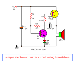
From the circuit in figure 1 will see that we use both transistors, which are matched pair transistors(CS 9012, CS9013), which works together with a few resistors, and capacitors. In as the oscillator circuit build sound signal frequency.
Figure 1: simple electronic buzzer circuit diagram using two-transistor
By has both resistors- R=1.2K and C=0.047uF to set the output frequency. Which can change slightly the value of both components, so the output sound changed. However, from the experiments, this value will be the best frequency.
The components list
Q1: CS9012: 50V 0.8A PNP Transistor
Q2: CS9013: 50V 0.8A NPP Transistor
*** for transistor please read the note:
C2-0.047uF 50V_Ceramic Capacitors
Electrolytic Capacitor
C1-33uF 25V or 47uF 25V or 10uF 25V
0.25w 5% resistors
R1-50K or 56K
R3-120Ω or 100Ω
R2-1.2K or 1K
LED: any color as you want
Piezo speaker,
9-volt battery Or 9V power supply circuit
PCB, and others.
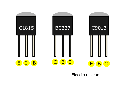
Transistors Equivalent
You can use any transistor number for example
NPN type: 2SC1815,BC547,2N3904
PNP type: 2SA1015,BC557,2N3906
But Position legs mismatch please be careful. as Figure below.
Read also: Electronic components list
Making Buzzer circuit
This project uses a few components and is easy. So you can assemble them on a perforated board or universal PCB board.
But if you would like to build PCB. You can also see the copper foil track layout of this project. (actual size) the prototype board as Figure 2 and Figure 3 is the components layout.

The bottom layout or Single-sided PCB layout
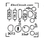
Components layout of simple buzzer circuit
This circuit use a voltage supply of 9V. So, normally it can use 6V to 12V.
All resistors use size ¼W.
Loudspeaker use size of 2 inches 8 ohms 0.25 W
You can listen to it in the video below.
Increase the buzzer loudness
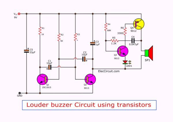
A Simple loud buzzer circuit (trembling sound) is creating a kind of ring circuit that provides a strange sweetness of general bell. It uses all-transistor so easy to builds and cheap, suitable for bedroom or a private room good or may be adapted into a bell. Listening to children play leisure. In addition melodic sound then. Also has LED light flashes with the beat shakiness of the sound as well.
The working principle
In the circuit, we will divide into two sectors work together. Firstly, as low frequency oscillator. Secondly, will be sound frequency oscillator.
On this second section include two transistors are CS9012, CS9013 are set as the audio frequency oscillator has out of 1200 Hz to a speaker. And some current from transistor will through to LED.
Trembling sound buzzer circuit
So, when the sound signal occurs. The LED1 will also glow. But The latter circuit will connect through pin C of Q2. So, if Q2 not conducted current, this circuit will not generate sound.
In that first section. There may be Q1 and Q2 connect together with R, C as the multivibrator oscillator.
They generate low frequencies of 5 Hz. So, Q2 will conduct and stop current with speed of about 5 Hz per minutes. It causes the second section generates a frequency out of sounds is approximated, sonorous, clear melodic quite vividly.
Building louder buzzer
This circuit use power supply of 9V. All resistors use ¼ W of size. The speaker 8 ohms size 2 inch 0.25 watts.
This project use a few components. So we can assemble on the universal PCB board. But we can make a PCB layout see as below. (LEFT)
Then, the wiring for circuit wiring and various components can view of the example in Right.
Watch out! carefully for is the polarity of the electrolytic capacitors and Pin of the transistors are not an error.
Single-sided PCB layout(left) and The components layout of this project. (Right)
The components List
0.25W Resistors, tolerance: 5%
R1: 1K
R2: 5K
R3: 2.7K
R4: 68K
R5: 1.2K
R6: 330 ohms
Semiconductors
Q1: 2SCC1815, C945, C458, NPN transistor
Q2, Q3: CS9013 or equivalent_NPN transistor
Q4: CS9012 or equivalent_PNP transistors
Electrolytic capacitors
C1, C2: 10uF 16V
C3: 1uF 16V
C4-0.047uF 50V, Ceramic
LED1: Any color as you want.
SP1: Speaker 8 ohms 2 inch 2 watts
Download This
All full-size images of this post are in this Ebook: Elec Circuit vol. 2 below. Please support me. 🙂
Siren Sound using transistors
GET UPDATE VIA EMAIL
I always try to make Electronics Learning Easy.
Related Posts

I love electronics. I have been learning about them through creating simple electronic circuits or small projects. And now I am also having my children do the same. Nevertheless, I hope you found the experiences we shared on this site useful and fulfilling.



What color led to use? Thanks
Hi, Billy
You can use LED any color as you want.
Hey guys I wanted to ask can there be a piezo or speaker? and yet how many roars? Thanks for the answer 🙂
Hi, Marek
You should normal speaker 8 ohms.
Thanks
Is it possible to control the buzzer frequency using msp430?
Can I use BC547 instead of CS9012?
Hi, Puja
No,You can use. you may use BC557 replace CS9012 because it same PNP type.
Wont work with BC547, BC557, 100 ohm & 56K… 🙁
Hi, thanks for the solution but how can I control the alarm sound for sometime like 45seconds?
thanks!
Yes, electrical electronics
Hello Emma,
Thanks for your feedback.
Apichet
Hi ElecCircuit, do you have pcb design for Transistor organ circuit?
Hello Joshua,
Thanks for your visit to my site.
Do you mean this circuit?
https://www.eleccircuit.com/keyboard-music-circuit/
Please tell me again which one.
I will design a circuit for you.
Have a good day.