We already learned somewhat about transistors through our experiments with transistors as switches. So today we’re going to adapt what we’ve learned for when using transistors in parallel with larger loads or when they consume a lot of electricity.
And we may have learned how to connect multiple transistors in parallel to support higher currents as well.

No Transistors for Larger Loads
In cases where we want to use a load that is larger than the transistor, for example, a 100W load with a 60W transistor, it won’t work as we have tried before.
We should use transistors larger than 100W for this, but we don’t have any. How can we solve this problem?
It reminded me of a quote: “Start where you are, Do what you can, Use what you have”, which I forgot where it came from.
We will start with what we have: many transistors with a size of approximately 60W, such as TIP41, MJE3055, 2SC1061, 2SD313, etc.
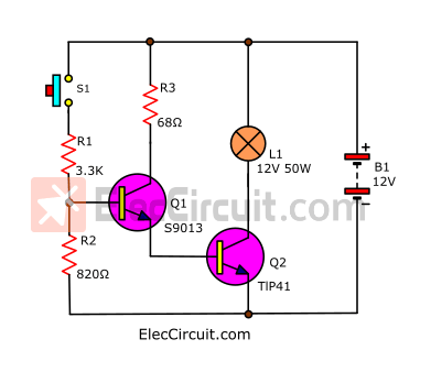
Experiment with a simple circuit
To begin with, we use a load that is a 12V 50W light bulb. Normally, it consumes about 4.16A, but the current measured about 3.3A. This may be due to an inaccuracy in measurement.
We put up a simple circuit with a TIP41 transistor, as shown in the picture below.
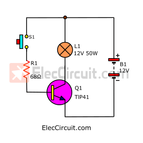
Find the value of R1
For better understanding, we recommend that you read the method for calculating R1 in the original article first.
Since we use a TIP41 transistor and a 12V power supply, each variable will be as follows: hFE=20, IC= 3.3A, VBE=0.9V, Vcc=12V
Therefore, the R1 value can be calculated.
Note: We set VBE to a higher value which increases the maximum operating efficiency of the transistor.
R1 = VR1 / IR1 ….(1)
VR1 = Vcc – Vbe
VR1 = 12V – 0.9V = 11.1V
IR1 is the current that flows through S1, which is the IB of Q1, so we can think of it as IB.
IB = IC / hFE
IB = 3.3A / 20 = 0.165
Therefore, substitute the values in formula (1)
R1 = 11.3V / 0.165A
R1 = 68.48 Ω
But it’s not in the Standard Resistor list, so we use the closest one, which is 68Ω.
The results of the experiment were quite good. L1 lit normally. We measured the VCE of the Q1-TIP41 to be approximately 0.55V.
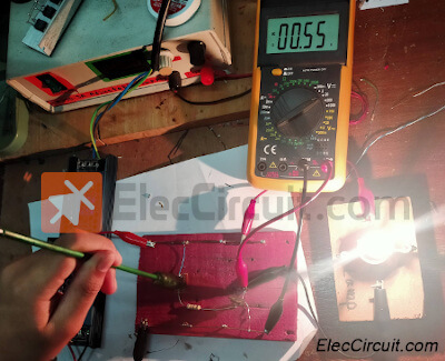
And the IC current of Q1 or L1 to be approximately 3.3A.
But there are two big disadvantages:
First, the IB, or current flowing through S1, is quite high. Normally, S1 can only withstand a current of about 0.1A.
The other is that although TIP41 can support a maximum current of 6A, the experiment with a current of 3.3A shows it reaches a very high temperature. For long-term usage, there will definitely be negative effects. Therefore, additional heat sinks should be attached.
Problems Solving
We’ll solve the first problem first. By adding another small transistor in parallel and the resistor, we can reduce current and stabilize the circuit. As shown in the circuit below (we rearrange the components a bit).
The diagram below shows the flow of current and voltage at various points in the circuit.
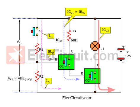
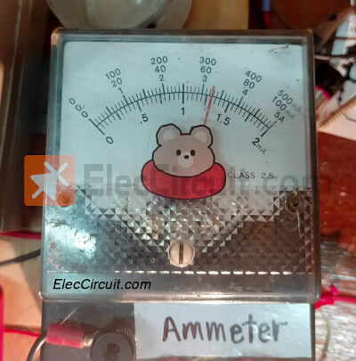
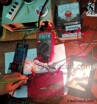
First, we put Q1 to work as a switch to replace S1 in the first circuit. We chose transistor S9013 because it can support the IC up to 0.5A, so it can withstand the IB of Q2 (IBQ2), which is only about 0.156A.
And you can see that IBQ2 is the IC of Q1, so it can be easily understood as ICQ1 = IBQ2.
Finding the values of R1 and R2
The next problem is that we want to know both the values of R1 and R2. In the past, we have used only one RB (resistor for reducing current using pin B), which is R1.
But from my experience, using additional transistors gives them a very high combined gain. So interference may cause it to misbehave.
We reduce this problem by adding R2. Both resistors work in a voltage-divider circuit. They help stabilize the voltage at R2 (VR2) or VBE of Q1 and Q2.
We will gradually solve problems based on what we know and what we have.
From which the relationship of the circuit can be summarised as follows:
There are 2 main formulas:
R1 = VR1 ÷ IR1 …..(1)
R2 = VR2 ÷ IR2 …..(2)
And what we see in the circuit:
VR1 = VCC – VR2
VR2 = VBEQ1+VBEQ2
IR1 = IR2 + IBQ1
What we know:
VCC = 12V since it is battery voltage.
VBEQ1 = 0.7V and VBEQ2 = 0.7V Since two transistor drivers work in a saturation state when VBE is approximately 0.6V to 0.8V. We choose a voltage of 0.7V.
So we can find VR2 by.
VR2 = 0.7V + 0.7V
VR2 = 1.4V
Now we’re able to find VR1 as well.
VR1 = VCC – (VBEQ1+VBEQ2)
VR1 = 12V – (0.7V + 0.7V) = 10.6V
Next, we’ll find IR1, but we should find IBQ1 first.
IBQ1 = ICQ1 ÷ hFEQ1
Where ICQ1 = IBQ2 = 0.156A, and the hFE of Q1-S9013 is approximately 60 to 180. According to our experience, when the IC’s value is low, it has a higher gain, so we use hFE = 100.
So,
IBQ1 = 0.15A ÷ 100
IBQ1 = 0.0015A
We can see that the transistor’s input requires very little current.
And we know that IBQ1 will flow through IR1, but part of IR1 will also flow through R2.
Therefore, it may be summarized as a simple formula:
IR1 = IBQ1 + IR2
or
IR2 = IR1 – IBQ1 …. (3)
So we try to set IR1 to be around 0.003A (3mA).
And substitute the value in (3).
IR2 = 0.003A – 0.0015A
IR2 = 0.0015A (1.5mA)
We substitute all values in formulas (1) and (2) the above.
R1 = VR1 ÷ IR1
R1 = 10.6V ÷ 0.003A = 3,533Ω
But it’s not in the list, so we use 3.3K instead.
R2 = VR2 ÷ IR2
R2 = 1.4V ÷ 0.0015A = 933Ω
But it also wasn’t in the list, so we used 820Ω instead.
At this time, the current flowing through S1 is very low, only 3mA.
But the second problem is that when Q2 works hardest, the current flowing through it is about 3.3A.
It is necessary to find a heat control solution. From what was said at the beginning, we can install a large heat sink for it.
But we want to develop ourselves. Learn how to solve a wider variety of problems. So we tried other methods.
From the above, we don’t have any other transistors that can withstand higher currents.
But we have many transistors of this type, such as TIP31, MJE2955, 2SC1061, and 2SD313. They have IC = 3A-6A max, hFE = 20 min, and VCE = 30V-60V max.
Parallel transistor circuit for more current
Suppose that the load requires a current of approximately 4A or more. What should we do? Let’s start by learning by experimenting with a simple circuit, as shown.
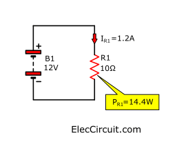
We tried connecting a 10Ω resistor to a 12V battery with a current flowing through the resistor of approximately 1.2A and calculated the wattage it used:
P = V x I
P = 12V x 1.2A = 14.4W
If you want increased current, we can normally do this in two ways.
- Increasing the current, but in this case we need to use only a 12V power supply.
- Reduce the resistance, but we don’t have a lower-value resistor.
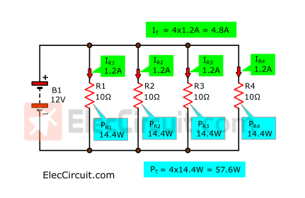
So we tried adding another 10Ω resistor connected in parallel with the other. Lowering their resistance to 5Ω, so they were able to handle more current, totaling 2.4A, with each still carrying the same 1.2A of current.
So we guess that if four 10Ω resistors are connected in parallel, as shown in the picture below,
Meet super transistor
It will cause their total current and wattage to increase to IT = 4.8A and PT = 57.6W, respectively.
From this experiment, we guessed that if the transistors are put in parallel, they will be able to handle higher currents as well.
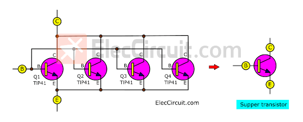
As per the diagram above, we put together each B leg, each C leg, and each E.
They instantly become super transistors.
As usual, each of the transistors is suitable for a current of about 1A, but when 4 of them work together in parallel, they can support a current of 4A, or about 4 times that.
So we tried connecting the circuit as shown.
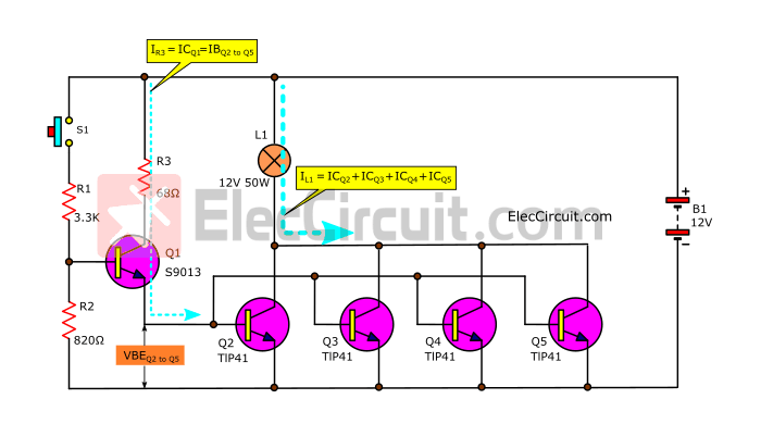
It’s quite simple. We just add Q2, Q3, Q4, and Q5.
We tried feeding it with electricity. The results showed that it worked well.
There are some notable points:
Current flows through the load at approximately 3.3A, the same as before.
- VR2 is about 1.5V, which is almost the same.
- The VBE of Q2 to Q5 is approximately 0.8 volts.
- ICQ1 or IR3 has a value of approximately 0.16A because the VBE of Q2 to Q5 does not change.
Question: When connecting multiple transistors in parallel, does their VBE change? We know through experimentation that its VBE is approximately the same as 0.6V to 0.8V.
However, the IC sent through by each of the transistors in parallel is reduced to only about 0.8A from the original 3.3A, or about 25%. We tested it for approximately 1 hour, and the temperature remained low to the touch and stable.
In my experience, a heat sink is only installed when the transistor is too hot to touch.
In this case, the size of the heat sink can be reduced, and the circuit will be more efficient.
Experiment 5V 4A up regulator circuit
From the results of this experiment, we can use it in many applications, such as driving large motors, DC 12V water pumps, solenoids, etc., and we will use an example circuit below to see a clearer picture.
We have made 12V to 5V DC converter circuits. This circuit can even supply currents up to approximately 3A.
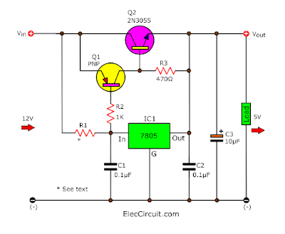
But if you need a higher current than 4A and its current cannot be higher than 3A. Because power transistors cannot amplify current that high.
But based on the results above, the parallel transistors should be able to solve this problem. So we tested the circuit as shown.
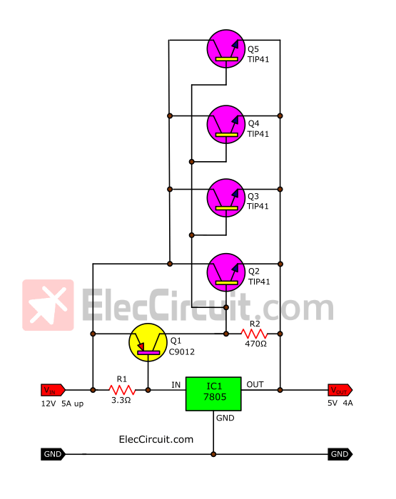
Buy TIP41 transistors at Amazon.com here (affiliated link)
The results of the experiment came out quite well. They can drive currents of more than 4A.
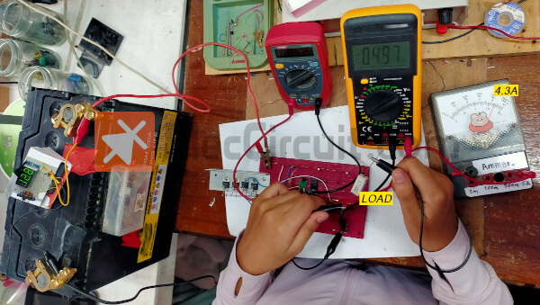
When we use a 1Ω resistor as a load, according to Ohm’s Law, it should draw around 5A. But we measured around 4.3A while the output voltage dropped to 4.95V.
And, when we tested it for a longer time, the results showed that the current and voltage remained constant, indicating that this circuit worked well.
Download This
All full-size images and PDFs of this post are in this Ebook below. Please support me. 🙂
Conclusion
From this experiment, we found that connecting several transistors in parallel can support higher currents, up to more than 100 watts, but with conditions. All transistors should have similar characteristics.
And it is worth noting that the total VCE level of the transistors in parallel will not exceed the lowest VCE level of the transistor that has the lowest among them. For example, TIP41 has a VCE max of 60V, but BU406 has a VCE max of 200V, so the total VCE level is only 60V. Otherwise, it may damage that transistor.
From our experience, they are always operated with only 30% of the maximum power they can withstand. For example, the total current they can withstand is 24A, or 288W max wattage (24A x 12V). But we use them with a current of about 5A, so they don’t get hot. So we can reduce the size of the heat sink, or sometimes there is no need to use the heat sink at all.
Another interesting point is from the experimental results: sometimes the current values do not comply with the principles or rules because the cheap measuring tools we used have low accuracy.
However, we have achieved our goal, which is that in the future, we will create electronic projects using parallel transistors to definitely amplify high currents.
Read next: Experiment with adjustable transistor circuits partially on-off

I love electronics. I have been learning about them through creating simple electronic circuits or small projects. And now I am also having my children do the same. Nevertheless, I hope you found the experiences we shared on this site useful and fulfilling.


Idei interesante.
Hi,
Thank you that you found this article interesting.
If you have any additional suggestions,
Please tell me, I like to learn it. 🙂