This is the Mini function generator circuit using ICL8038. (Precision Waveform Generator/ Voltage Controlled Oscillator). It will generate output 3 waveform, Sine wave signal, triangle, and square wave signals.
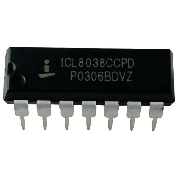
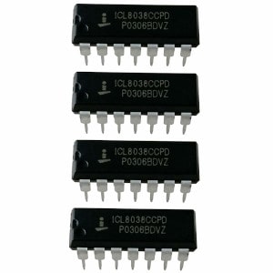
Look at ICL8038 or ICL8038CCPD DIP-14 Precise Waveform Generator Voltage Control Oscillator. It looks like LM324 op-amp but its function difference.
Why use it?
It is useful IC.
Imagine we need a function generator circuit. We have many ways to do. Using the ICL8038 waveform generator is a great option.
I want you to see the picture more clearly.
Suppose that you just made a power amplifier. It is so nice sound. But some said that It sounds distorted.
You know the best amplifier circuit increases a sound up only. It must not change frequency and waveform of that sound.
We have an oscilloscope to see the waveform.
But we should use an input sound that can change any waveform and frequency.
The function generator is a great helper.
Because…
Product high accuracy sine, square,
triangular, sawtooth and pulse waveforms with a minimum of
external components.
Give the frequency (or repetition rate) from 0.001Hz to more than 300kHz using either resistors or capacitors.
Have frequency modulation and sweeping with an
external voltage.
and more…
Features
• Low Frequency Drift with Temperature . . . . . 250ppm/oC
• Low Distortion . . . . . . . . . . . . . . . 1% (Sine Wave Output)
• High Linearity . . . . . . . . . . .0.1% (Triangle Wave Output)
• Wide Frequency Range . . . . . . . . . . . .0.001Hz to 300kHz
• Variable Duty Cycle . . . . . . . . . . . . . . . . . . . . . 2% to 98%
• High Level Outputs. . . . . . . . . . . . . . . . . . . . . . TTL to 28V
• Simultaneous Sine, Square, and Triangle Wave
Outputs
• Easy to Use – Just a Handful of External Components
Required
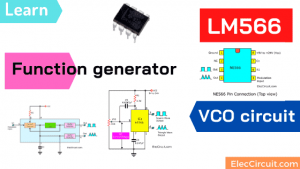
ICL8038 Pinout
Want to use it? We need to know pin connection. Or we called pinout.
Look: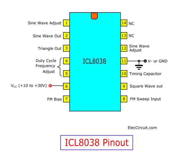
Basic circuit
The output of this circuit is quite realistic in the waveform. And we will suggest a 2 model include
(1.) the basic model
(2.) the improved performance model, we can customize even more.
If you are interested, don’t wait. Let’s see it below!
Basic diagram ICL8038 circuit Function generator
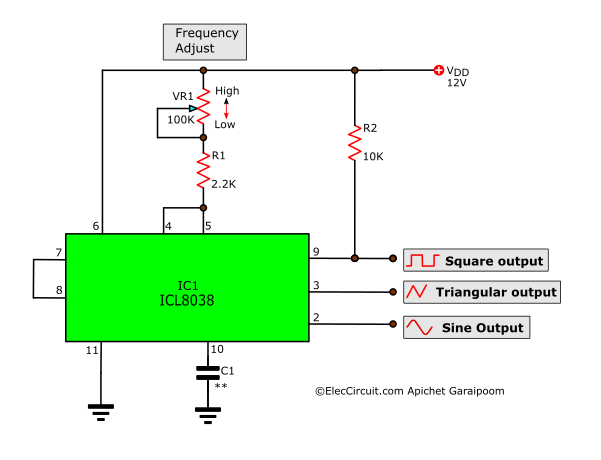
Figure 1 The basic circuit of function generator using ICL8038
The Basic characteristics of the circuit with a few components, it consists of the VR1-potentiometer, the R1-resistors and the C1-capacitors to determined frequency output. We can use the below formula to calculate the frequency output as follows.
The Frequency output (f)
= 0.15/(VR1+R1)C1…….(1)
First, If the waveform is not symmetrical. The output of IC1 can be modified as follows. Secondly, we connect the 500 ohms-resistors across pin 4 and VR1. Then, connect pin 5 with VR1 just done.
The first circuit will be cheaper. It has low performance.
We recommend creating a second circuit for real use. It adds slightly parts.
The components list
Resistors size 1/4W 5%
R1: 2.2K
R2: 10K
VR1: 10K Single potentiometer
Capacitors
C1: See in text
Semiconductor
IC1: ICL8038, Precision Waveform Generator/ Voltage Controlled Oscillator
Socket IC, The Universal PCB Board, and other etc.
How to builds
You can build this circuit on universal PCB board on Figure 2. the wiring, and various components can see carefully. For the devices has various polarity should be careful in the assembly circuit.
They include the electrolytic capacitors, potentiometer, resistors and Pin of the IC is not an error.
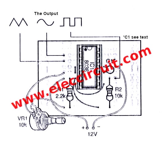
Figure 2 the components layout of the basic circuit.
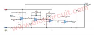
Developed ICL8038 function generator Model
But if the model is developed as in Figure 3. May have to invest a lot. Which device has the additional duty is different. But the important point is to make circuit more stable and Adjustment to the desired waveform.
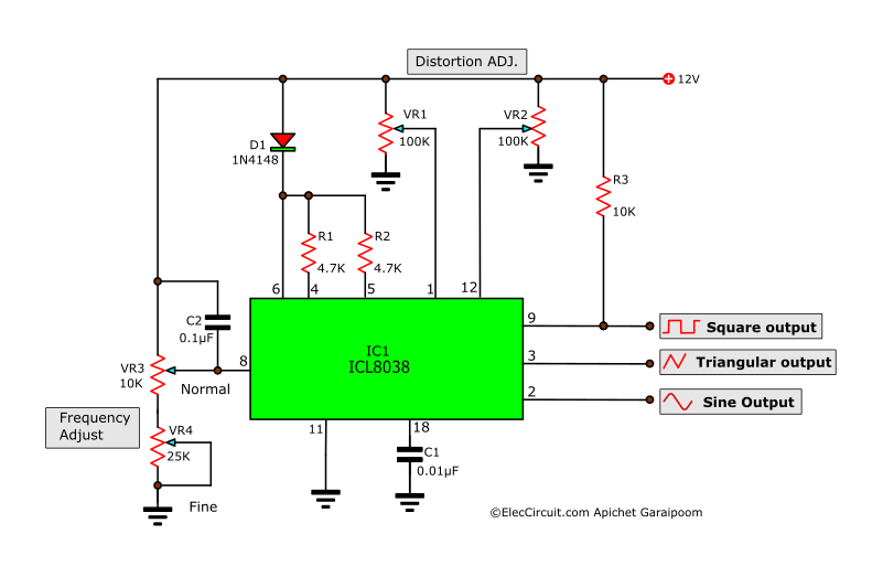
Figure 3 the circuit diagram of the model is developed.
After that, We come to understand the equipment to do it. Started at D1, R1 and R2 are the control output of signal has a symmetric or duty cycle at 50%. The VR1 and VR2 to adjust the waveform at the output is a distortion of the original signal. The VR3 is used to select the desired frequency at the output and Finally is VR4 is used to obtain the highest frequency there. For the C1 of both circuit Be used to determine the frequency of each district varies as Table 2.
Table 2 the value of capacitor-C1 that use in each frequency range of the function generators
Frequency range _____ C1 value
1Hz – 100Hz: 1uF
100Hz-1KHz: 0.1uF
1KHz-10KHz: 0.01uF
10KHz-100KHz: 0.001uF
The all capacitors using to withstand voltage at 25 volts, And If you want this machine provides output from lowest to highest by Without changing C1, It’s not hard, just to pin 10 of IC1 with various values of C1 into selector switches. You are now a Mini function generator that has the output of 3 model. Them to informally
How to builds this projects
We can build this circuit as Figure 4 as the components layout on the universal PCB board. Which looks like building the project by mins ago project.
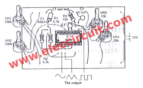
Figure 4 the components layouts of these projects.
The components list.
Resistors size 1/4W 5%
R1, R2: 4.7K
R3: 10K
VR1, VR2: 100K(B) Dual potentiometer
VR3: 10K(B) Single potentiometer
Capacitors
C1: See text
C2: 0.1uF(104) 50V Ceramic
Semiconductor
D1: 1N914 or 1N4148, 75V 150mA Diodes
IC1: ICL8038, Precision Waveform Generator/ Voltage Controlled Oscillator
Note: There are affiliate links on this post. This does not change the cost of the item for you. Thanks for your support.
Socket IC 14 pin, Universal PCB board.
This circuit requires enough power supply. Do you have this one? If you do not have it. Look:Learn Many Power supply circuits
GET UPDATE VIA EMAIL
I always try to make Electronics Learning Easy.
Related Posts

I love electronics. I have been learning about them through creating simple electronic circuits or small projects. And now I am also having my children do the same. Nevertheless, I hope you found the experiences we shared on this site useful and fulfilling.
what is the amplification level generated by this circuit?? how to vary the amplitude levels?
Regarding Figure 1 schematic: There is an error in the wiring of the schematic: Wired as shown will burn the ICL8038:
Pin 6 needs +V and NOT pin 5. Pins 4 and 5 should be bridged.
Hi Peter Well spoted
I noticed this problem this moring after blowing one chip up
I have yet to test the circuit with the right connections in place
Thanks
Hello!
If you want to make the best Schumann generator, what is for you the best chip? ICL8038? XR2206? Can you please hep me? Thank you.
Francisco
Hello,
Would you provide boards for the ICL8035 generator?
Thank you!
Francisco
Helo,
Can you please supply the gerber files?
Thank you.
Francisco
Thank you… Thank you… Thank you,
your circuit will help me too much, because I am creating a free energy generator, & for that I am creating the mechanic part, & as I know, absolutely nothing at the electric part, your help is welcome.
Thank you again, best regards,
Paul Baroud
Hello
could you help me? I would like to drive a LED with a 8038 choosing from the 3 different wave forms and with a frequency range from 0.3 to 20 Hz
could it be done?
Hello,
Yes, You can use ICL8038 for this. It is quite easy.