When you watch the movie Hollywood. You hear the siren on many police cars. It is a very familiar sound. We also build our own police siren circuit. It is easy to do that. They have 3 circuit ideas for you.
- 555 police siren circuit—simple and cheap
- European police siren circuit—using 555 and transistor so easy.
- Police Bicycle siren circuit OP-AMP—another idea, interesting, too.
Police siren circuit using 555 IC
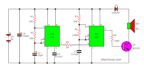
In the circuit diagram, use IC1 in an astable multivibrator mode. It produces a low signal frequency, comes out of pin 3 about 1 Hz. The frequency value is controlled by R1, R2, and C1.
Then, this signal gets into pin 5 of IC2 through R5. You will see that the frequency from IC1 is combined with the frequency of IC2. Also, this frequency is controlled by R3, R4, and C3.
Next, the mixed signal about 440 Hz – 550 Hz flows out of pin 3 of IC2.
After that, R6 pass this signal into the base of Q1. It will increase the current of the signal to a speaker. Then, the speaker makes a very loud sound like a police siren.
Recommended: How does NE555 timer circuit works
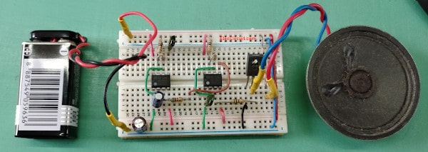
Build police siren circuit using 555
This circuit is not designed PCB layout. If you do not want to design own PCB.
Or using universal PCB Board is difficult.
You can assemble the component to the breadboard as below:
And listen to the sound of siren here.
Components list
IC1,IC2_NE555 timer= 2 pcs.
Q1_BD139, 80V 1.5A NPN Transistor = 1 pcs.
Electrolytic capacitors
C1_10uF 25V = 1 pcs.
C4_100uF 25V = 1 pcs.
Ceramic or Mylar capacitors
C2_0.1uF 50V = 1 pcs.
C3_0.01uF 50V = 1 pcs.
0.25 watts, tolerance: 5%, Resistors
R1,R3_10K = 2 pcs.
R2_75K = 1 pcs.
R5_5K_= 1 pcs.
R4_220K_= 1 pcs.
R6_150 ohms = 1 pcs.
D1_1N4007, 1000V 1A Diodes_= 1 pcs.
Speaker 8 ohms = 1 pcs.
B1: 9-volt battery Or 9V power supply circuit
European police siren generator circuit
The European police siren circuit is the type of a siren. Which it is strange and different from normal. The characteristics sound is very high – low.
You may try to build this circuit. Because it used popular components, IC-555, small transistors, and basic parts. It may be suitable for amateur electronics.
The working principle
In the circuit below will divide working into 2 section. Which I will describe to section 2 first.
In this section, IC1- 555 is the frequency generator. With connecting of a few components, R-10K, and C-0.033 µF. Also, the value of R and C will set an output frequency of about 1,450 Hz.
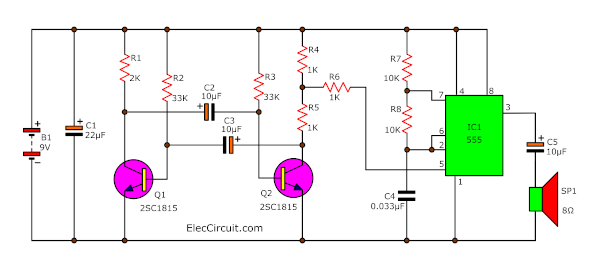
Then, this signal gets out of pin 3 of IC1. To enter into the speaker through C-33µF.
The frequency that IC1 produces for this unless it is determined by the value of R, C then, Can also be set by the input voltage into pin 5 of IC1. Mean that we can change the frequency by changing the voltage at this pin 5.
With this features, in section 1 will produce a low-frequency of about 2-3 Hz. Then, use voltage from low-frequency to controls the pin 5 of IC1 again.
So, the sound comes out of a high and low frequency alternating indefinitely. The center frequency is around 1,450 Hz.
Builds European police siren circuit
This circuit uses a 9V power supply from the battery. All Resistors is 0.25 W. The speaker is 0.25W 8 ohms, 2 inches.
The PCB layout of the actual size with the components layout as below.
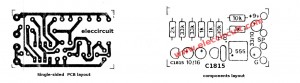
The Single-sided PCB layout and Components layout of European police siren circuit
Note:
The IC-555 is produced by several companies. The code letters on the front, not the same. If the number 555 is to be used with it. Such as NE555, LM555, SA555, HA17555, MC555, etc. it.
Components list
IC-555 timer-8 DIP = 1pcs.
TR_C1815 transisotor = 2 pcs.
Electrolyte Capacitors
C-33uF 16V = 2 pcs.
C-10uF 16V = 2 pcs.
C-0.033uF 50V _Polyestor capacitors
0.25W 5%_Resistors
R-1K = 3 pcs.
R-10K = 2 pcs.
Other components see in the circuit.
Download This Post as a PDF and all PCB layouts

Police Bicycle siren circuit OP-AMP
Here is another siren circuit idea. Bonus! It is a police bicycle siren circuit. It uses an op-amp circuit as main parts.
Note: This circuit has not been tested.
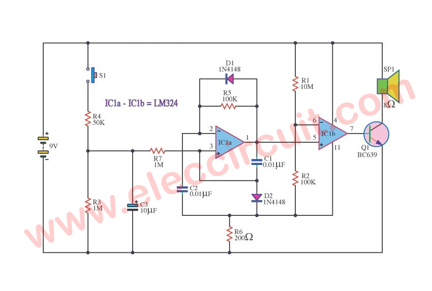
The Police Bicycle Siren circuit diagram
The principle works
This circuit is the Sound generator. While still does not press S1. It will have no the loud sound comes out of a loudspeaker SP1.
When press S1 then release. C3 charge the current to full. While pressing switch S1. And it will discharge current go out. When releasing S1. The current from C3 will flow through R7 to trigger 3 pin non-inverting of IC1a.
IC1, D1, D2, C1, C2, and R5 produces sound generator signal. Then it comes into pin 6 of IC1a to reach at pin 3 (Non-inverting) of IC1b. Which there are R1 and R2 are a detector.
For do fining level has signal then signal to come out of pin 7 of IC1b. To bias the base of Q1-BC639.
Q1 is working to make a very loud siren sound to a speaker. Then, C3 discharges to finished, SP1 stop making the siren.
Two-tone Alarm circuit using LM3900
This is two tone alarm use op-amp IC, LM3900 (Quad Amplifiers). It produces the frequency of square wave in 2 level. It is high frequency and low then mix the sound in the end danger beep.
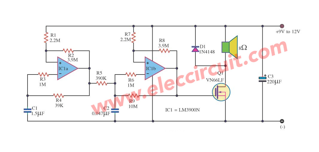
It is appropriate it has can to link up a loudspeaker with ,using power mosfet then have better use transistor which complicated and not durable. This circuit convenients for power supply 9V to 12V sizes and 8-ohm 20watt size loudspeakers will by large-sized have a voice loud small-sized better.
‘Keep reading: High power siren circuit ’ »
GET UPDATE VIA EMAIL
I always try to make Electronics Learning Easy.
Related Posts


I love electronics. I have been learning about them through creating simple electronic circuits or small projects. And now I am also having my children do the same. Nevertheless, I hope you found the experiences we shared on this site useful and fulfilling.
#Police Bicycle Siren circuit
can u give me working principle of siren light circuit
hi. I want a Digital Clock Circui Diagram.pls send a diagram.
Hi, soumen
Please see this:https://www.eleccircuit.com/cheap-digital-time-clock-with-alarm-circuit-by-lm8560/
simple digital clock.
#Police Bicycle Siren circuit
is this circuit really works on bread board or not??
Thank you…..
Actually it’s working nice.
The IC I had used ,was defected.
Thanks,
K.kausik
Hi, k.kausik
Thanks for your feedback.
Please show your project’s photos.
We want to see it and happy to you.
Hi, what is the wattage of the speaker?
#Police Bicycle Siren circuit
this circuit reminds me of my ex
Is there any way to add some LEDs in this circuit to light up when the siren goes off?
Do you have any circuit diagram for the car siren of Ghostbusters (ECTO II)?
I love this and I need more circuit diagram I will be constructing them soon for my project
Is it a legal issue to upload video to youtube on how to build a police sirene based on your schematic?
I am struggling to build it if you have a clear HD video on the construction of the police siren please send me a link