Let’s create a Non-contact AC voltage detector/tester circuit. Around five years ago, I taught my son to build this circuit.
And now my daughter also wants to make it. It is a very useful circuit, uses to detect if the AC main wires or any electrical appliances have electricity in them or not.

For how to build, let’s look at the one my daughter has made.
She tells her grandpa that this thing is a ghost detector! LOL
We have created both the transistor and the IC version. Of cause, you can build it as well because the components used are easy to find. My daughter already made one, which means you can make it too.
But first, we have to understand what a non-contact voltage detector is and how it works, then how to make one.
Why use these circuits?
Electricity has many uses but it also comes with great danger, especially AC lines. If we become unaware of it, It might cause us a life-threatening injury.
Therefore, we must concern about our safety first when dealing with AC lines or high voltage electricity.
Before working with AC wires, Electrical boxes, AC main power supply, or others of the same types. We should test if it still has electricity running through.
Since the electricity can not be seen with a naked eye. So, we need a tool to detect if it is there or not. Which, there are many tools to start with such as
- The multi-meter with a range set to AC voltage can measure the voltage between AC wires well enough, but it is quite complicated.
- The next tool is popular among electrical (including me). The neon screwdriver or Tester screwdriver, Test Lamp Screwdriver.
The Neon Screwdriver
It is a simple tool used to test if objects or conductors have electricity inside them or not. It is also used to check electrical appliances for leakage.
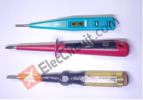
The common neon screwdriver operations
The inside consisted of a neon lamp connected to a resistor with very high resistance. It will limit the current that flows through the neon lamp and our body making it non-dangerous.
To use, we just grab the handle of the screwdriver. Then touch the tip of the screwdriver to the exposed metal part. It will be a closed-circuit by the AC voltage will flow from the tip of the screwdriver through the neon, Resistor, and our finger of the body to the ground. The neon will glow when the voltage reaches a certain level.
But I avoided having my daughter use the neon screwdriver to measure the AC main because it touches the conductive metal directly, it is very dangerous if we are not skilled enough.
The solution is to use a Non-contact voltage detector circuit instead.
What is a Non-contact voltage detector?
It is an AC voltage detector, that can be used to test live wires without any connection, hence the name.
Therefore, it is safer than the neon screwdriver when tested on AC wires and lowers the chance of getting an electric shock while working with high AC voltage.
How does Non-contact voltage detector circuit work?
Usually, there will be an electric and magnetic field surrounding a live wire created by the flowing of AC current. We can use this phenomenon to detect if a wire still has current inside it, by using an antenna as a detector. Which is the main principle of these circuits.

If you want to read about the electric field in depth. You can search further at Wikipedia.
When we put the antenna near AC wires if it detects a magnetic field around that wire, the LED will glow dimly and at the same time, the buzzer emits a high frequency buzzing.
The nearer the antenna from the AC wires, the brighter the LED will get. The buzzing of the buzzer will also be louder.
During the testing process, we should avoid letting the antenna touch the wires directly.
Let’s Create Non-contact voltage detector circuits
There are two versions of these circuits in this post. The difference is one of them uses transistors as a core and another uses CD4060 instead. Their function is the same.
My daughter chose to build a circuit that uses transistors. because it is easy to create (It’s easier to solder the components) and it’s also easier to understand how the circuit works.
Transistors Version
The antenna will converter the magnetic field into a very very small amount of current, and then amplify it with a very high gain amplifier.
This amplified current will then power a LED or buzzer for our visual or sound feedback.
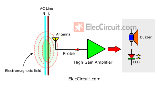
For the High gain amplifier, we pick the Darlington Transistor pair because it is easy and high efficiency. To make it easier to understand see the illustration below.
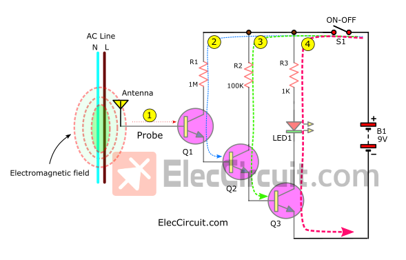
Here is a step-by-step process.
- #1 The antenna inducts very little electrical energy or AC main signal that frequency of 50Hz (60Hz) into B of Q1.
- #2 Makes a higher current flow through R1, C to E of Q1.
- #3 Next a higher current flow through R2, C to E of Q2.
- #4 Finally, the highest current flow through R3, LED1, C to E of Q3, causing LED1 to glow or flash.
My daughter said it was easy to understand. It works like a tiny water valve, controlling the next big water valve more and more.
The current gain of the Darlington pair is equal to the gain of Each of them (Q1, Q2, Q3) multiplied together. If uses BC547 NPN type with popular to use in many circuits. They have about 8,000 gains. so, they have a very high sensitivity.
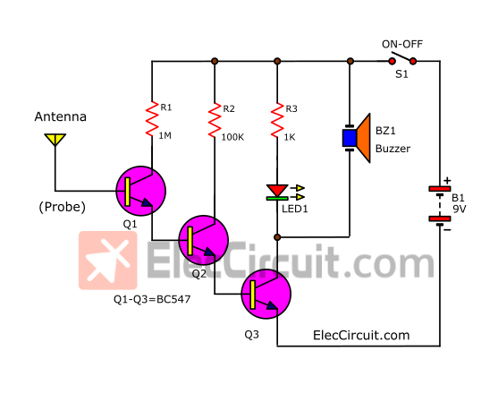
Then, see the full circuit diagram. We add a piezo buzzer across LED1 and R3 to emit an alarm to indicate hum tone as the AC main frequency.
This era is very convenient, if you want a buzzer sound, use only one. It has its own buzzer circuit, reducing the circuit to less. My daughter likes it very much.
Read also many simple circuits for beginner
How to build it
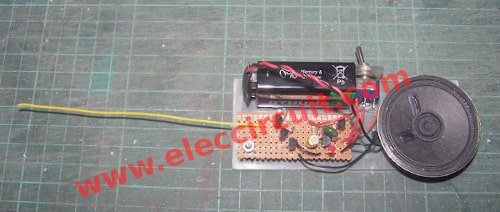
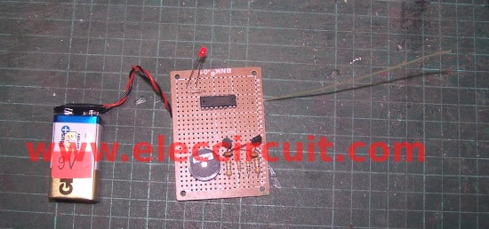
This circuit is very simple. My daughter assembled it without using the normal PCB. She soldered the pins together. Then, place it on a piece of cardboard. However, if you want to assemble it onto the Perforated PCB as well.

Here is The prototype of the non-contact AC voltage detector circuit was built by my daughter.
Components list
Q1-Q3: BC547, 0.4A 40V NPN transistors, 4 pcs.
0.25 watts Resistors
R1: 1M, 1 pcs.
R2: 100K, 1 pcs.
R: 1K, 1 pcs.
LED1: Color as you want, 1 pcs.
BZ1: Small Piezo Buzzer 3-26V
S1: SPDT switches on-off, 1 pcs.
9 volts battery Or 9V power supply circuit
Some friends used to ask if they don’t have BC547, can they use other transistors? Yes, you can use any NPN transistor type such as BC546, BC548, BC550, or BC337. Or other forms such as S9013, 2N3904, PN2222, 2SC1815, etc. But the position of its pins is different as shown in the illustration below.
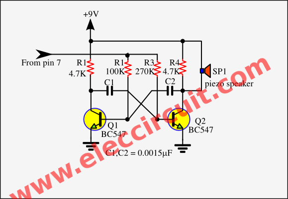
However, if you have old components or don’t want to use a piezo buzzer. You can build it in the old way. It is louder because using larger speakers.
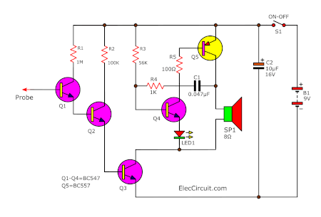
See a complete circuit diagram of this project. We see that and are happy since it is simple as well.
The simple buzzer please read Make simple electronic buzzer.
The component list
Q1-Q4: BC547, 0.4A 40V NPN transistors, 4 pcs.
Q5: BC557, 0.4A 40V PNP transistors, 1 pcs.
0.25 watts Resistors
R1: 1M, 1 pcs.
R2: 100K, 1 pcs.
R3: 56K, 1 pcs.
R4: 1K, 1 pcs.
R5: 100 ohms, 1 pcs.
C1: 0.047uF 50V, Ceramic capacitors, 1 pcs.
C2: 10uF 25V, Electrolytic capacitors, 1 pcs.
LED1: Color as you want, 1 pcs.
Speaker 8 ohms, 1 pcs.
S1: SPDT switches on-off, 1 pcs.
9 volts battery
In this project, we can assemble them on a perforated PC board. We do not need to set it since no potentiometer, just press S1 to turn on then already to use so well.
In the video below we will see when to take this tool near the electromagnetic field such as the Main, Lamp, monitor, Microwave, laptop, computer and etc. LED1 will flash and we hear a hum tone sound.
IC version
This circuit can be used the same way as the transistor circuit version. But use IC1(CD4060) instead, it is a CMOS chip that acts as both a frequency generator and a 14-stage binary frequency counter.
This IC is suitable for this kind of usage because its input has a very high resistance. Thus, making it very sensitive to a faint electric signal and capable of counting multiple frequency stages.
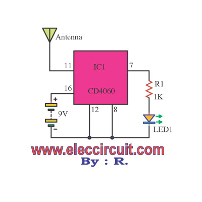
When we put the antenna close to AC wires, the electromagnetic inducts into pin 11 of IC1 as a clock signal.
Suppose the AC Lines have an electric current with a frequency of 50Hz (or 60Hz in the USA). It is then divided frequency by 16, equal to 3Hz, out of the pin 7(Q4) of IC1 which is connected to the LED1. Then, the LED1 will flash at the speed of 3 times per second, indicating that there is an electric field surrounding the AC wires.
But if there is no voltage or current inside the AC line, then the IC1 will not output anything. The LED1 will not blink. Instead, it will be left in either an on or off state.
This voltage detector project can also be used to detect the magnetic field at various points such as a monitor, lamp, TV, computer, and more. The LED1 may flash faster depending on the intensity of the magnetic field and the higher the frequency, the faster the LED will blink.
Read Also: Stray Magnetic field meter circuit
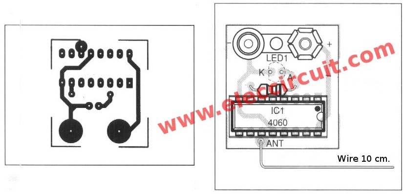
When we started to use a wire antenna is a length of 10 cm. Placed near the conductor insulation. Then, the electromagnetic inducts into the clock signal to pin 11 of IC1-CD4060.
Read next: CD4060 timer 22S to 4Hr
This is a CMOS as a frequency generator circuit and 14 stage binary frequency counter.
The electromagnetic field from the mains power. Which has a frequency of 50HZ come to IC1. It is frequently divided out of the Q4 pin of IC1. It is divided by 16, frequency equals 3HZ.
So the LED1 flashes to indicate that around the mains power.
Recommended: Morning sun alarm circuit using IC-4011
Here are a few related circuits you may want to learn:
- 4 Peak voltage tester circuits using op-amp and 723
- How Motorcycle Capacitor Discharge Ignition CDI works | example Circuits
- Temperature detector circuit with buzzer alarm
It is so easy and safe to uses. Just you place the antenna close to the mains cable or plug socket.
If it has an electric current, LED1 will flash. But if no power, LED1 is lit or shut down. As mentioned above.
Update:
I add a buzzer circuit at the output. As the circuit below and see video show using this project.
The buzzer sound circuit is an astable multivibrator with both transistors like we often use them.
And We assemble them on the universal PCB board as Figure 4
All components please see in a circuit it a few parts.
My son is testing the non-contact voltage detector circuit.
When near AC-line it will alarm with buzzer sound and LED flash as the frequency of AC-line.
And can test areas that high frequency or fluorescent lamps.
I have been building and publishing this circuit for many years. There are many websites to test these circuits, For example. makingcircuits, jameco So, we are confident that these circuits are performing well enough to become popular.
Battery is important
The circuit works best when the battery is full. This circuit only consumes about 7mA to 10mA thus It can be powered by a common 9V battery.
We can not guarantee how long will the battery last. Usually, we only use it for half a minute at a time. Under this circumstance we expect it to last for a couple of months.
If you are willing to carry around a 12V battery, then it definitely lasts longer.
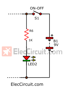
We intend to use the components only as needed. But If you are worried about whether the battery is weak or not, we can add the simple battery voltage indicator circuit with an LED.
Conclusion
Remember: Do not insert the antenna into of plug socket or touch to AC main directly. This circuit will damage and we will also danger from high voltage.
The downside of this project is that it cannot indicate which is Line or Neutral. But I think it is not so important. Because it is budget effective, It is worthwhile to build it.
You also may like circuit
- Continuity tester circuit with Buzzer and LED
- 2 Crystal tester circuits with PCB
- Simple transistor tester circuits
GET UPDATE VIA EMAIL
I always try to make Electronics Learning Easy.
Related Posts


I love electronics. I have been learning about them through creating simple electronic circuits or small projects. And now I am also having my children do the same. Nevertheless, I hope you found the experiences we shared on this site useful and fulfilling.
#IC version
This is A Really Handy Dandy Circuit to Have around in Your Shop,,Many Thanks to the Designer of This Project!!!
Simple..Cheap to Build and Useful,,What else can I ask For!!
#IC version
I built This Circuit And It Doesn’t Detect AC,,,,, Only In My Fingers<<<WHY?????
#IC version
Has This Been Tested??
#IC version
Does This Circuit WORK?? I tried it with NO LUCK!!!
#IC version
This circuit work. They small parts.
What A Handy Dandy Little Tester To Have..It Could Very Well Save Your Life One Day!!!!
Hi,MR OHM 1970.
Thank a lot for your feedback.
thank you very much for these great projects
Hi, Walusimbi frank.
Thanks for your feedback.
#IC version
I Will Build It Again!!!!
sir,
I find your ckt. very useful for safety(AC) but it would be good to have a similar one for DC(600V) Also.
can you provide that ckt. for DC also?
Thank you in advance.
#IC-version
I built it. It works. BUT ONLY IF TOUCHED TO AC TERMINALS (be there any resistance or not). Do not try this without insulation. I tested by touching my soldering iron tip. It blinked.
#IC-version
Keeping inputs of a CMOS IC floating is a bad idea, it will soon damage the IC
Excellent. Absolutely loved reading and very helpful at the same time 🙂
Respected Sir/Madam I wandering for a long time this type of circuit making on it a normal vero board, Sorry to say I make it 2 time properly but it’s extremely failed. I will try it one more time, let’s see what happen. Thanks for the idea.
Hello Manoj Dhali,
It is a circuit built with fun. We will notice different levels of tones. When the antenna is placed near the AC power cord.
Low gain transistors may not run well.
I hope you try to build other circuits. These circuits are simple. but increases our learning well.
Thank
Thank you for your schematics. Do you have any ideas on how to build an antenna tuner for standard international short wave radios?
I appreciate your comment.
But I apologize we do not have these circuits on our website at the moment. Now that I start teaching my daughter electronics, maybe in the future if she has interested in short wave radios. I have also wanted to create these types of circuits for a while now.