These are the digital clock generator circuit and 60Hz oscillator, both were using MM5369 and crystal. So, they can be used as a calibrator for standard frequency. They also give 1HZ, 1/60Hz, and 3.579MHz at TP (Test point).
The clock generators use MM5369 – 8 pins as the main component and can be used with a 12V power supply. In regular use, the output pin 1 gives a standard frequency of 60Hz.
What is a clock generator circuit?
The clock generator circuit is an oscillator circuit that produces a clock signal for use in synchronizing a circuit’s operation. Read more meaning on clock generator in technical terms.
For us as hobbyists, our clock that we used to watch the times daily. It requires standard time which set it to run correctly. We will create this clock generator circuit to synchronize with standard time. This frequency has to be as accurate as possible, or it can cause you to be late for work (clock error). This circuit generated the frequency at 60Hz in the square waveform.
60Hz oscillator circuit
Imagine when we have finished creating our digital clock circuit. Some circuits use a standard frequency signal of AC power line, which in North America is 60Hz (60 cycles per second or 60 Hertz).
But when we need to use it in the car or with other DC power supplies.
It would not work in this case.
Or, even we need to use the 60 Hz standard frequency for many digital counter circuits.
How can we solve this issue?
We so built a 60 Hz pulse generator circuit, to replace the old circuit. Also, we may integrate it with a backup system. When the power goes out, we do not have to waste time recalibrating it again.
Recommended: ECG simulator circuit using CD4521 and CD4017
MM5369 High Precision 60Hz oscillator
We have many digital clock generator circuits to choose from. But we pick this circuit because it is easy to use, and prove to be reliable.
It is a CMOS IC with 17 binary divider stages. We can use it to generate a precise reference. By using commonly available high-frequency quartz crystals.
Cr: Photo ElectronicStorm
Features
- Crystal oscillator
- Two buffered outputs
- Output 1 crystal frequency
- Output 2 full division
- High speed (4 MHz at VDD e 10V)
- Wide supply range 3V–15V
- Low power
- Fully static operation
- 8-lead dual-in-line package
- Low Current
Read next: ICL8038 Function Generator circuits
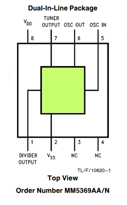
MM5369 pinout
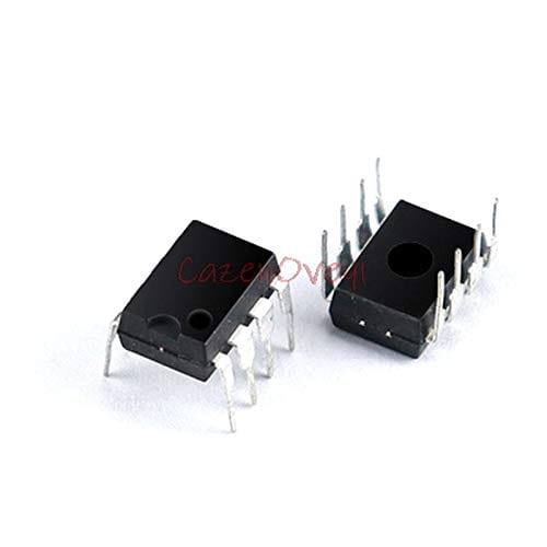
The MM5369 is available for an 8-lead dual-in-line 8 DIP (Similar to the 555 TIMER) epoxy package.
An internal pulse is generated by mask programming the combinations of stages 1 through 4 16 and 17 to set or reset the individual stages.
See MM5369 pinout.
Read also:
How 60Hz oscillator works
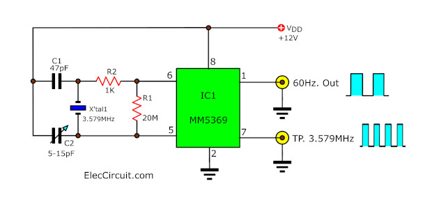
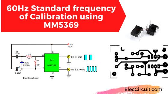
In the working heart of this circuit are the MM5369-IC and the crystal oscillator with a frequency of 3.579 MHz as shown in the circuit above.
The signal output of this circuit has 2 frequencies
- 60Hz main usage
- 3.579 MHz is a crystal-generated frequency, which can be adjusted a little bit by the C2 trimmer
The detail of the parts
IC1: MM5369AA
X-Tal: 3.579 MHz
R1: 20M, 0.25W Resistor 1%
R2: 1K, 0.25W Resistor 1%
C1: 47pF 50V, Ceramic capacitor
C2: Trimmer 5-15pF
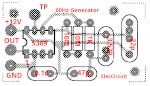
How to build
Assemble all components as a circuit diagram into PCB layout as below. Then, adjust C2 until the output pin 7 (TP) is equal to 3.579000MHz as shown in a frequency meter.
If you do not have the frequency meter. Try to connect it with a real digital clock circuit. If the frequency is low. The clock will move slower than usual. On other hand, if the clock frequency is high, the clock will tick faster.
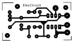
The PCB layout
The Component layout for the PCB
Clock generator circuit
This circuit is for producing a standard frequency for a digital counter circuit inside the digital clock in particular. As they require high accuracy frequency in the square waveform.
This circuit is more appealing than the circuit above. Since the output frequencies have 3 choices to choose from as follows 60 Hertz, 1 Hertz, and 1/60 Hertz. This is convenient for use on the time bases circuit such as a counter, a timer, digital clock circuits, etc.
How to clock generator circuit works
Look at the circuit below
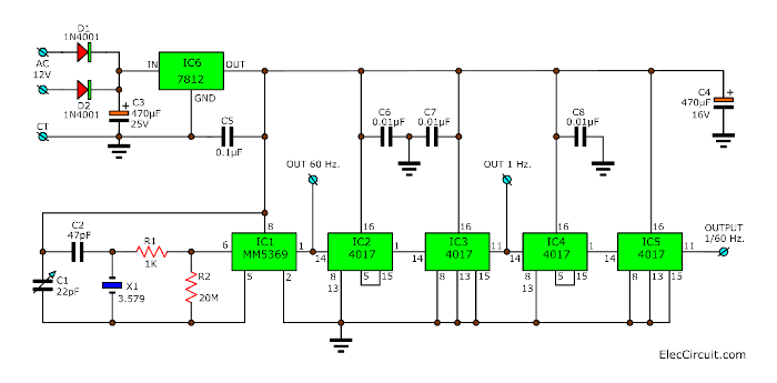
The working heart of this clock generator circuit is MM5369 to generate a clock frequency (standard digital clock) of 60Hz.
Because we use the crystal frequency of 3.579 MHz to determine a fixed value of frequency. Therefore, the output is very accurate.
The output signal of 60 Hz at pin 1 of IC1 can be used immediately. Especially, apply to the general digital clock circuit. It can be used directly.
But if we need the lower frequency output. We need to apply this signal to the frequency divider circuit (IC2 to IC5 are CD4017) first.
And, this circuit requires a 12V regulated power supply only. We do use the 7812 regulator IC to keep the voltage to be stable.
- 1Hz output
The output from pin 11 of IC3 will has a frequency of 1Hz. - 1/60Hz output
The output from pin 11 of IC5 will has frequencies of 1/60 Hz (1 cycle per minute )
We can use AC voltage from 12V to 18V of the center trap (CT) transformer. And, apply directly to the input by diodes D1 and D2, they work as a rectifier AC to DC. Then, smoothen the DCV with a C3 capacitor filter.
Then, you get to the clock signal that has an amplitude of about 12 volts as you want.
Here are a few related articles you may want to read:
- LM8560 Digital clock circuit diagram with alarm
- LM8365 digital clock circuit board
- CD4060 timer circuit, 22 seconds to 4 hours
How to build a clock generator circuit
All components of this circuit can be assembled into a PCB layout as below. When finished assembling the circuit, the next is to test it with a frequency meter similar to the circuit above.
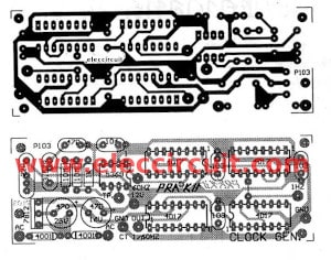
The single-sided PCB layout and the Component layout for the PCB
The components List
IC1: MM5369AA
IC2, IC3, IC4, IC5: CD4017
IC6: LM7812, DC regulated 12V-IC
D1, D2: 1N4001, 50V 1A Diodes
R1: 1K: 0.25W 1% resistors
R2: 10M x2, 0.25W 1% resistors
C1: TRIMMER capacitor 22pF
Polyester Capacitor
C2: 47pF
C5: 0.1uF 50V
C6, C7, C8: 0.01uF 50V
Electrolytic Capacitors
C3: 470uF 25V
C4: 470uF 16V
Note:
However, If you think that this circuit is not good enough for you.
You can see the crystal circuit is as follows:
- 5 Crystal oscillator Circuits using Digital ICs example 1Hz standard digital clock, Pulse generator 32.768kHz using a watch crystal.
- Transistor crystal oscillator circuits: example: Oscillator astable multi-vibrator with Crystal controller
Download This Post
All full-size images and PDFs of this post are in this Ebook below. Please support me. 🙂
GET UPDATE VIA EMAIL
I always try to make Electronics Learning Easy.
Related Posts

I love electronics. I have been learning about them through creating simple electronic circuits or small projects. And now I am also having my children do the same. Nevertheless, I hope you found the experiences we shared on this site useful and fulfilling.
hi dear
i am looking for MM5369EYR 250 pcs.
ivant to work 50hz. can you help me ?
immediately.
thanks and regards.
Does this 60 Hz circuit have a 12 V A/C input? Is the 60 Hz output pulse 12 V?
Yes, you may use LM350 to drive 3A output current. https://www.eleccircuit.com/high-power-pulse-generator-using-lm350t-and-ne555/ This idea, you may apply its output of this circuit instead of 555.
Thank you for your prompt answer. I have been running around with my questions lol.
Another question – Can the output of this circuit be used as an input to a d/c cdi to pulse an ignition coil at 60 Hz?
I have a 12v battery running your cicuit. The output of this circuit is 6.3V at 250mA and that is going to a lm2596 buck converter to boost the 6.3V to 12V to be the trigger of a CDi to trigger an ignition coil. The problem I am having is the 6.3V at 250mA will not trigger the lm2596 dc buck converter. Any assistance would be greatly appreciated thank you.
What a handy dandy circuit(s). You have here!!!! These circuits are great for testing frequency counters!!! Thanks again. Rick
Hey Rick,
Thanks! We are happy that you like these circuits. 🙂
Will this work with a battery pack of 22vdc to provide 22vac at 60hz?
Hi,
Usually it doesn’t. But my dad and I experimented with adding a circuit so it could do what you want.
Go to: https://www.eleccircuit.com/lm317-power-switch-controller/
It may not be 100% perfect, but it can always be improved in the future. 🙂