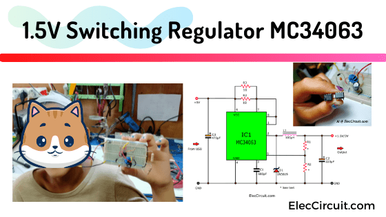
Today, I’m going to introduce a circuit that performs higher than before. And you will like it like me. It is a 1.5V Step down Switching regulator using KA34063/MC34063. Imagine you have an old MP3 player it needs a 1.5V battery.
But you only have the power bank, USB port 5V output. Sure, it doesn’t work. Therefore, this circuit is a good solution.
If you need 1.5V voltage for small portable devices. We usually use a 1.5V battery. But sometimes it’s inconvenient. Now, a USB port is very popular. It will be great if use that. But it is 5V. We need to convert it down to 1.5V stable voltage.
The circuit ideas
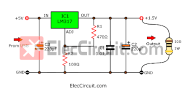
In the past, I used LM317: 5V to 1.5V converter circuit. Because it is easy to use and cheap. But it’s low efficiency. How? let me explain to you
Look at the circuit below.
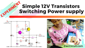
Now, I am teaching my daughter to learn electronic circuits. She likes to learn by experimental methods. To understand step by step (Slow brain, both father and daughter). Hope it will be helpful for you too. Let’s learn together.
Trying LM317 doesn’t work
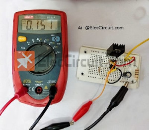
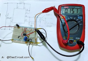
We add a 10 ohms 1W resistor to the output as load.
Is the level of output voltage constant? let’s measure the voltage.
As a result, the output voltage drops to about 1.4V.
what happened? Then, We measure the load current. According to Ohm’s law principle. When Voltage is 1.5V, resistance is 10 ohms. The current flowing through it is 0.15A (1.5V/10ohms).
Learn: How does NE555 timer circuit work
But in this case, the current drops slightly. Because the voltage decreases, the current also decreases to 0.139A as shown below.
It still works! But Do we want what better?
Learn next, We measure all currents of this circuit. It shows 0.151A.
Recommended: Learning Electronics for beginners!
Some of the currents disappeared. Because the LM317 needs it as Adj. It is too little until you can ignore it.
Look at the block diagram below. We will understand more.
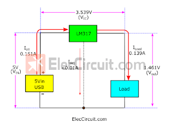
It looks like LM317 and Load are connected in series. Therefore, each device has the current flowing through only one current, approximately 0.15A.
Notice: The voltage drop across the LM317 is about 3.5V high. Therefore, more than 50% of the power is wasted. (Approx. 0.15A x 3.5V = 0.52W)
To be clear, let’s increase the input voltage is 12V. As expected, the voltage drop across the LM317 is approximately 10.5V.
Thus a power loss of 1.57W Oh..too high. Although, the output power is about approx 0.225W only.
For all these reasons, We should find a better alternative.
That is a switching power supply. It includes a switching chip and an inductor or capacitor. To generate the output voltage and current.
It is more efficient, produces an output with a lower or higher voltage than the supply. Even it can increase the current higher. (We will learn together in the next opportunity.)
Don’t get confused, let’s look at a lower voltage first! 🙂
We called a Buck regulator in short.
Buck regulator
It needs a high input voltage, to power a low output voltage.
Some called a buck converter, step-down DC converter, step-down switching regulator.
Read before: DC to DC Buck converter working principle in basic!
In a short time, how does it work?
Inside, a buck regulator has a high-frequency oscillator to turn a transistor (or FET) on and off. To send a lot of energy to an inductor. Then, the transistor turns off, the energy from the inductor is stored in an output capacitor to load.
Interesting features: It will take a high voltage at a low current. Then, convert it to a low voltage at a high current. For example: Convert 12V @ 0.5A to 5V @1A, Or even Convert 5V @ 0.08A to 1.5V @0.15A (in this post read below).
Sure, It is more complicated than an LM317. However, we can do it in a simple way, my daughter can do it, and you too.
Look at the block diagram below.
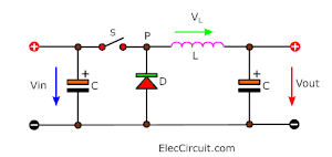
It requires only a few external components to create a complete supply, which are inductor, capacitor, diode, and switching (S).
The S is the important part of the chip. There are many chips to uses. Some are high-power but too expensive compared to LM317. In the final, I take MC3406 or KA34063.
Some of the components are inside the chip, including complex details such as the switching system, transistor, comparator, and more. It makes our work easier and more convenient. It has a 1.25V reference regulator part that also looks like the LM317. We can connect to the output to monitor the voltage and maintain stability.
Well, it may be enough. You might start to get bored.
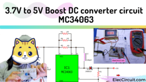
1.5V Switching Regulator circuit
Next, Let’s make a 1.5V Step-up Switching regulator circuit.
My daughter is complaining that she does not like learning complicatedly about how circuits work. Is it possible? We select or configure a device without a deep understanding of it.
Yes, it might be possible. IC manufacturers also want it to be easy to use. He will introduce how to use it easily in the datasheet.
Interested components
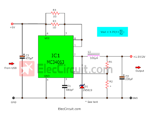
R1&R2: set the output voltage.
At pin 5 is a 1.25V detector. When the voltage across R2 is 1.25V. The chip will shut down.
Vout = 1.25(1+R1/R2)
This formula is similar to the LM317, thus the original resistor values can be used.
| Voltage Output | R1 | R2 |
|---|---|---|
| 1.5 V | 100Ω | 470Ω |
| 3 V | 470Ω | 330Ω |
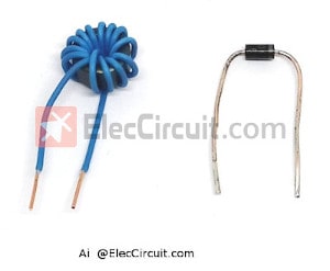
D1: High-speed Schottky Diode
This circuit operates at a very high frequency. Approximately no more than 100KHz. Therefore, use High-speed Schottky Diode. We pick 1N5819 is Schottky Rectifier, 40 V, 1 A because cheap and most popular.
Note: We have tried 1N4007 (normal rectifier Diode) with the same effect. If you don’t have 1N5819, give it a try.
L1: Inductor
It is an important component is in all switching regulator circuits. In the datasheet, it states 170uH, 220uH, 100uH.
Some people have problems using it or can’t find it. We are the same. But keep in mind that it’s a coil. It’s that simple!
We try to wrap the wires on the ferrite core. Then try it! It turned out to be as good as it seems.
Look at below. Example ferrite core that we use. It is most commonly found in compact fluorescent lamps.
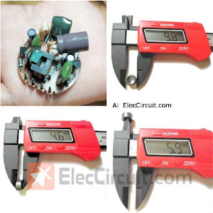
My daughter measures a ferrite core 9.8 mm in diameter, 4.6 mm thick, and 5.9 mm.
Then, wrap approximately 10 turns of 24AWG solid wire on the ferrite core.
Read next: DIY inductor coil from compact Fluorescent Light
C2, and C3 filter capacitors
It’s another important device. It serves to store electrical energy in the power supply circuit. We used to test C2 and C3 values of 10uF. The result showed that the voltage dropped to 0.8V-0.9V. It is below the specified limit.
When we change C2 and C3 to 100μF to 470μF, the voltage goes up to 1.5V stable. It’s exactly what we calculated.
However, even if we increase it to 1000μF the voltage stays the same. But the current is slightly more stable. It’s not worth it (more than necessary).
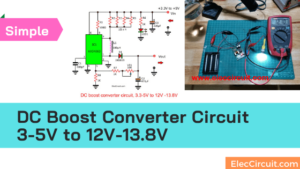
Circuit Performance Test
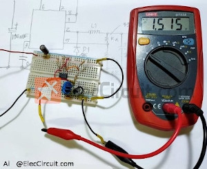
Then, let’s test it. Assemble the entire circuit onto the breadboard.
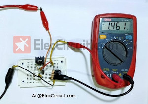
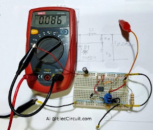
First of all, measure the output voltage while no load. It results 1.515V exactly as specified.
Then, add the load, 10Ω 1 watts resistor. And measure the output voltage again. It shows 1.5V. Great! The voltage drops a little bit only.
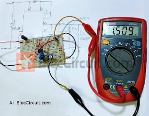
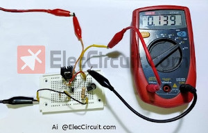
Measure the load current. It is right! It shows about 0.151A, (1.515V÷10Ω).
Is there anything better than the old one? Measure next, and we’ll know!
We measure the current of this circuit (Vin). It shows about 0.085A. Yes! the current is lower than LM317.
We want to see a clearer picture. Let’s compare!
| Cases | MC34063 | LM317 |
|---|---|---|
| All currents used | 0.085A (Good) | 0.151A |
| Output voltage with load | 1.509V | 1.46V |
| Output current with load | 0.151A | 0.139A |
| Time/Power bank 10,000mAh | 117 hours | 66 hours |
From the table above, if we use it with a 10,000mAh Power bank, we can use the load for almost 2 times longer.
When replacing the input voltage is 12V. The input current is reduced to only 0.056A. With the load still working, the output voltage remains constant, 1.5V @ 0.15A.
It shows that this circuit is better than the original circuit. because it uses less current as of the input voltage increases. Of course, it doesn’t get hot while working, too.
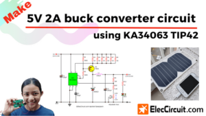
Read more: How to increase more current for chip 5V 2A buck converter
Is it worth it? to switch to this chip. In the future, we will try to increase the output current level, hope this article will be helpful to you.
Download This Post
All full-size images and PDFs of this post are in this E-book below. Please support me. 🙂
Related Posts
GET UPDATE VIA EMAIL
I always try to make Electronics Learning Easy.
Related Posts

I love electronics. I have been learning about them through creating simple electronic circuits or small projects. And now I am also having my children do the same. Nevertheless, I hope you found the experiences we shared on this site useful and fulfilling.
Easy to understand Switched Mode Power Supply & it’s basic principle. Very interesting to assemble with the available components.! – Thanks a lot.!