I always teach my children how to plant a tree, which typically begins with a vegetable in small pots. Even if we used the best fertilizer, if we forgot to water the plants, they would have died in no time.
On the other hand, if we water the plants too much, it may cause their roots to rot or cause other diseases. Thus, maintaining the soil’s humidity is very important for our plants.

That’s why we are going to build this Simple Solar Plant Watering Alarm Circuit, or a Simple Solar Powered Soil Humidity Alarm Circuit, with the following features and attributes:
1. A buzzer alarms when the soil’s humidity decreases.
2. Be as energy-efficient as possible.
3. Only sounds an alarm during the day; if it sounds at night, it can be disruptive to our neighbor.
4. Uses low-cost and basic components.
5. A simple circuit that is suitable for learning basic electronics.
Circuit Design and Choosing Components
We can use the requirements that we set out earlier as a guideline for designing and choosing parts for the circuit that are as appropriate and efficient as possible.
Main Block Diagram
Now, let us summarise the components required to assemble a circuit with the desired functionality into an easy-to-understand block diagram.
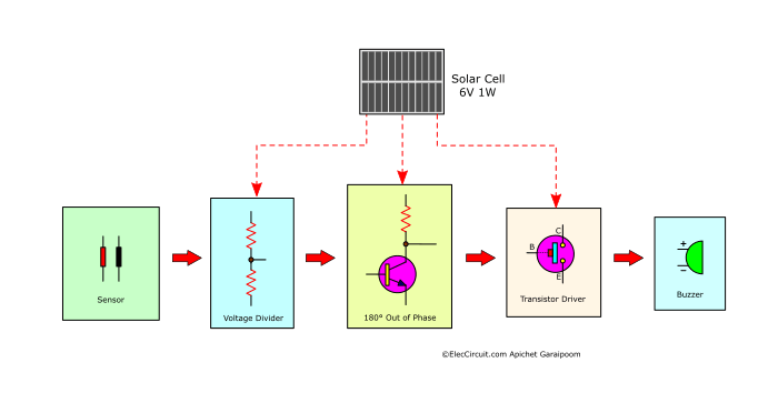
Buzzer
We chose the small active buzzer, which is very easy to operate; just supply it with 1.5V to 12V. The sound level will depend on the voltage level, but we only need medium, so we will be using a voltage of 5V to 6V and a current of just about 10mA.
Solar Cell
Since we only plan to use this circuit during the day and to conserve energy, we will be using the 6V 1W solar cell to power it. During peak sunlight, this solar cell can supply a maximum of 0.16A (1W/6V).
The Driver Transistor
Even though the buzzer that we choose only requires a very small amount of electricity, it is still recommended that we use a driver transistor to power it because it is easier to control it in various ways. In the example circuit below, the transistor is acting as a switch.
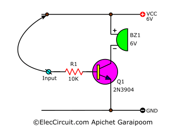
When we apply current to the input, the resistor reduces it before it flows to the transistor and activates it. Thus, current can flow through the buzzer, causing it to emit noise.
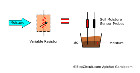
The Sensor
Next is the sensor that we will be using to measure the humidity in the soil. The simplest way to do this is to use two electrically conducting metal probes that measure the humidity of the soil between them.
You can think of it as a variable resistor that changes its resistance depending on the soil’s humidity. If the moisture in the soil is high, then more electricity conducts between the two probes, resulting in lower resistance, and vice versa. So we can assume that resistance is directly related to soil humidity.
The Voltage Divider
To read the output of the sensor, we would have to connect it in the form of a voltage divider circuit, which we simply do by adding in another resistor to it. And when we take a measurement of the output voltage of this voltage divider circuit, we see that it increases as the humidity increases.
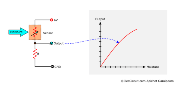
So if we combine all of the parts above, we will get this circuit:
Wet soil alarm circuit
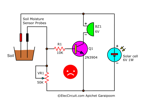
But it would not function as we had anticipated; the buzzer will emit noise when the humidity level is high, contrary to what we want.
180° out of phase
To solve this, we would need to reverse the signal, or a 180° out of phase, from the voltage divider block before entering the transistor diver circuit.
The easiest way is to use a common-emitter transistor amplifier circuit.
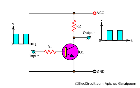
The main idea behind it is that the output will have the opposite signal as the input, which is also why it is so popular.
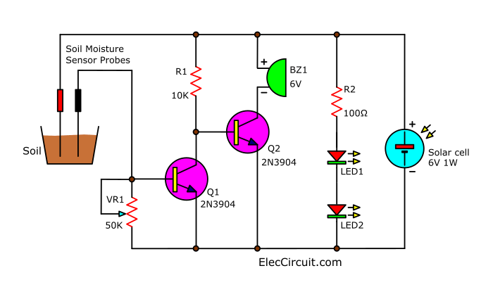
So if we integrate this common emitter transistor with the circuit earlier, we will get a fully functional circuit as we desired.
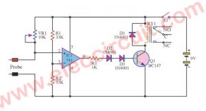
Learning How the Circuit Works
Now let’s understand how this circuit functions. Though you might already know that the circuit will only work during the day because it is powered directly by the solar cell, we can still divide its operation into two scenarios.
In the case of high humidity
(1) The current from the solar cell flows through R2, LED1, and LED2, causing both LEDs to light up, indicating that current from the solar cell is flowing into the circuit. The reason we use two LEDs connected in series is to check the voltage level of the solar cell.
As we might already know, each LED needs around 2V of voltage and 10mA to 20mA of current to work. Therefore, if both of them light up, it means that the solar cell produced at least 4V, as anything less will cause both LEDs to turn off.
Aside from this, we also add R2 as a current-limiting resistor, whose resistance is found through:
R2 = Vsolar – VLEDs / ILed
R2 = (6V-4V) / 20mA
R2 = 100Ω
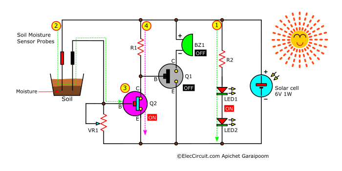
(2) When the soil is wet or has high humidity, current can easily flow between the sensor probes, much like a resistor with very low resistance. This results in more base current flowing into Q2.
(3) Causing the Q2 to work, similar to an ON switch.
(4) Thus, the higher current will be able to flow through R1 and C-E of Q2 to the ground. At the same time, there would be no base current for the Q1, so it would remain off, causing the BZ1 (buzzer) to turn off as well.
In the case of low humidity
(2) Conversely, when the soil is dry or has low humidity, the resistance between the probes is high, resulting in a decrease in the base current flowing into the B of Q2.
(3) Preventing Q2 from functioning, similar to an OFF switch.
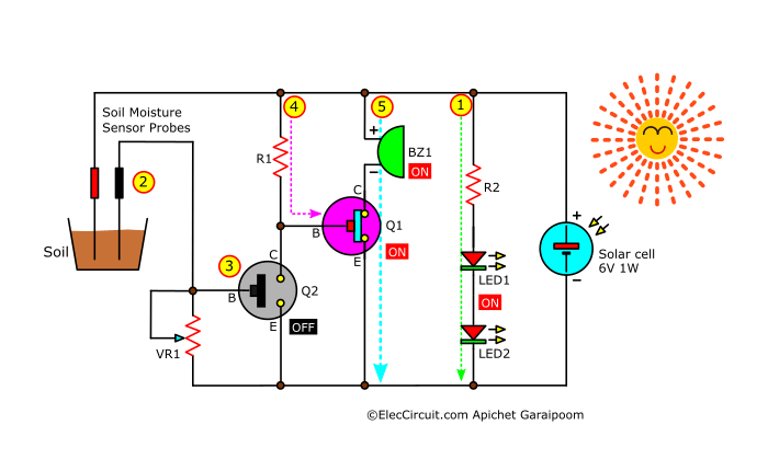
(4) The current coming through would instead flow to B of Q1, which would turn it on.
(5) Thus allowing a larger amount of current to flow through from C to E of Q1 and powering the buzzer.
The conductive material we use as a sensor probe is regular stainless steel wire because it is very good at withstanding corrosion and oxidation, which may affect the functioning of the circuit. As for the sensitivity of the sensor, you can adjust it by changing the distance between the two probes or using the VR1.
Want more brilliant ideas? Here’s how to get them through electronic circuits.
How to build
My children have built this circuit twice already, with each time having a different way of putting the circuit together.
Parts will you need
Q1,Q2: 2N3904, 40V 0.2A NPN Transistor
LED1, LED2: 3mm Red LED or others
R1: 10K 0.25W Resistors tolerance: 5%
R2: 100Ω, 0.25W Resistors tolerance: 5%
VR1: 50K Potentiometer
BZ1: 6V(1.5V to 12V) Active Buzzer
Solar cell: 6V 1W
Wires, and others
Assemble on cardboard
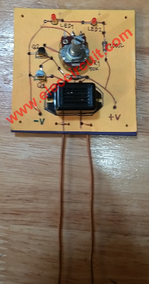
About eleven years ago, my son built this circuit by assembling the components on a piece of thick cardboard.
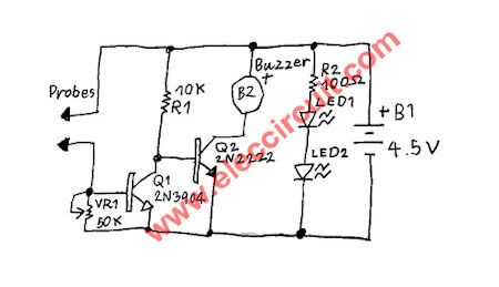
And as you may have noticed, the Q2 in this version is 2N2222 instead of a slightly cheaper 2N3904; they both have the same pin layout and can be used interchangeably. At first, he tested this circuit with a 4.5V battery (AA 1.5Vx4).
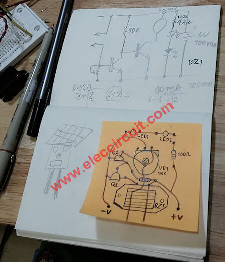
He drew the component and wiring layout on small 3×3-inch paper. Imagine that it is the face of the robot, the eyes of the robot are the two LEDs, the potentiometer is the nose, and the buzzer is the robot’s mouth. On top, he will install the solar cell as shown in this illustration.
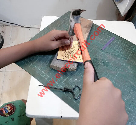
Then, glue the piece of paper with the layout on it on top of a thick piece of cardboard from an unused tabletop calendar. And after the glue has set, use a hammer to drive a hole through the cardboard so that we can put in the components.
Bend a leg of a component and twist them together to create a joint. If the leg would not reach, then use small copper wires, sized around 24 AWG, to join them together. And solder each of the connected joints.
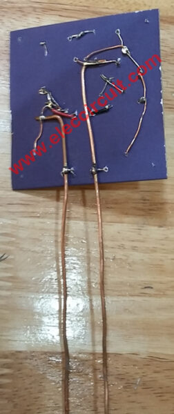
As for the sonsor probes, he uses a 3 mm copper wire, around 20 cm in length. So that he can run through the ground, it can also be interpreted as the leg of the robot.
Lastly, mount the solar cell panel on top of the circuit.
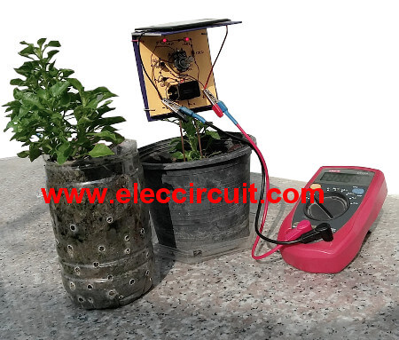
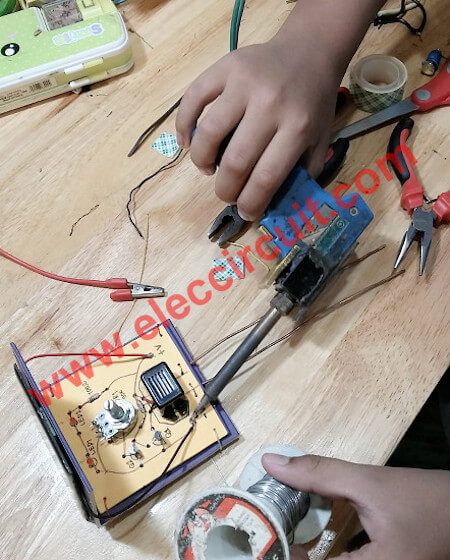
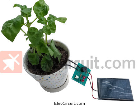
Now that we have finished building the circuit, we put it to real use, which you will be able to see in the video below.
We also tweaked both the distance between each probe and the VR1 for the best sensitivity for our plants.
Note:
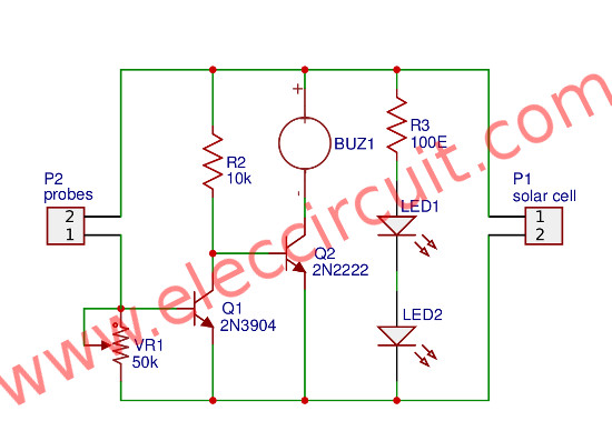
If you want to build the PCB for this project. My son design it below.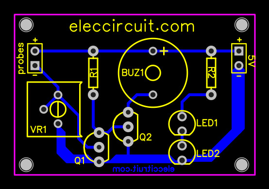
Component layout
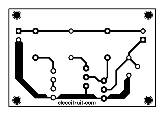
Actual-size of Single-sided Copper PCB layout
Assemble on perforated PCB
Recently, my daughter has also built this circuit, although now she has assembled it on a perforated PCB, making it smaller and more rigid.
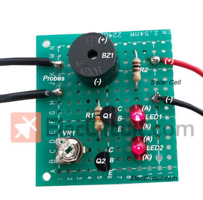
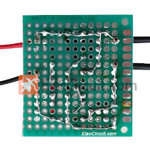
She has been using it for a few months now, and it works as well as the one her brother made a few years ago. But in the future, she might build a new and improved one.
Read more This is better: Small Automatic Plant Watering with a Solar Cell Power System
Conclusion
This circuit worked quite well, but there are many ways to improve it, such as adding a duration-adjustable automatic watering system. So that no matter how large or small a plant is, it will receive an adequate amount of water.
or see the smaller circuit: Simple soil moisture alarm circuit diagram using 1.5V battery
GET UPDATE VIA EMAIL
I always try to make Electronics Learning Easy.
Related Posts

I love electronics. I have been learning about them through creating simple electronic circuits or small projects. And now I am also having my children do the same. Nevertheless, I hope you found the experiences we shared on this site useful and fulfilling.
Thank you very much.
nic
love you site,
could you draw a circuit including your plant sensor to open a 12 volt water solenoid and turned off when the plants and sensor was wet.
when the plants in my mini hot house need water can the sensor tell the power to open the water solenoid
the misting sprinklers spray the plants till the sensor is damp and it stops.
if you can do this can you email me regards Vin thanks
Water tank atomaiti
My number 9170014001 up se hu plz help me
Hi divyanshu chaurasia
Please go to :
https://www.eleccircuit.com/simple-automatic-water-level-controller-circuit/ (Easy but work)
https://www.eleccircuit.com/automatic-water-tank-using-pump-controller-by-2sd882/
https://www.eleccircuit.com/plant-soil-moisture-meter-and-automatic-controller-circuit/
https://www.eleccircuit.com/simple-high-level-water-alarm/
Can you tell me any substitute for 2n3904 transistor as I am not finding it
Hello Tanay R,
Yes, you can use a lot of NPN transistors, such as BC548 or 2SC1815. But they may be different the pinout. Be careful when you assemble it.
Bonjour.
Félicitation pour l’ensemble du travail de vulgarisation que vous faites
Hello,
Thanks for your feedback.