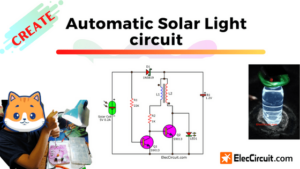
These are the outdoor solar light circuits. If we need lighting around our home at night. But those areas are without an AC line because it is hard to do the wiring there. And we also want to save on electricity costs.
So, we came up with the idea to build a solar light circuit diagram. With the basic components, we have a 12V battery, LED lamps, and a solar cell.
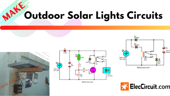
At night, the LED lamp will light up with power from the 12V battery. But during the day, sunlight enables the solar cell to generate electricity. And causing the LED to turn off, and the 12V battery gets charged with enough current to power the LED at night.
We have two circuits that we would like to introduce to you. They are simple and economical in concept. We can use the basic electronic components we have.
Simple 12V Solar Lights Circuit
We will start with the simplest circuit ideas for an LED circuit and a solar charger circuit.
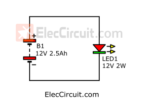
Simplest LED circuit
First, we use a 12V 2.5Ah battery and a 12V 2W LED. The LED consumes about 0.16A (from 2W/12V). At night, we need about 8 hours of light. So, the LED needs about 1.28A in total, or around 50% of the battery capacity. So it should be enough.
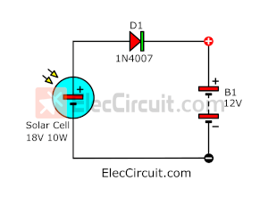
Simplest solar charger circuit
Second, during the day, we have about 5 to 8 hours to charge the battery. When using an 18V 10W solar cell, it discharges about 0.5A in 5 hours, giving a total power of about 2.5A. That should be enough to charge the battery.
Even a 60% charge is enough for the LED to stay on almost the entire night because our LED has low power consumption.
In the schematic circuit diagram, we add D1 to have the current flow into the battery and not out.
How Simple Solar Light Circuit Diagram Works
Why is there an on-off switch on solar lights?
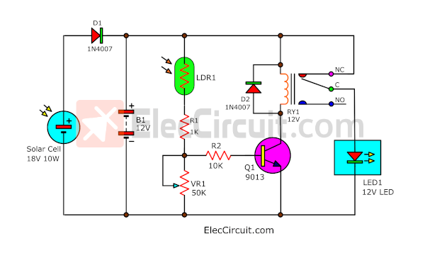
Next, we need to add an automatic LED controller. We chose the relay because it is easy and can control high-current loads. When the voltage is applied to the coil. The switch inside it operates as a Single-Pole Double-throw (SPDT) switch.
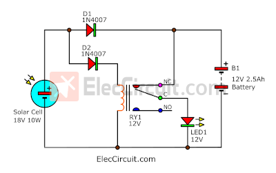
According to the circuit above, suppose that during the day the solar cell’s voltage flows through D2 to the relay coil. It then causes switch contacts C and NO to touch. Thus, the battery current cannot flow through the switch contacts ( NC to C) to the LED to GND. LED1 is immediately turned off.
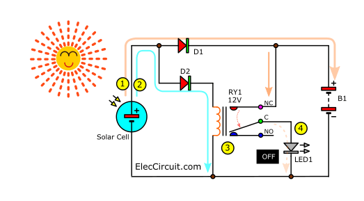
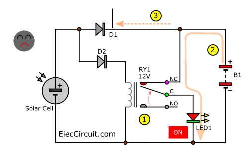
But on the other hand, at night, the relay coil no longer receives the voltage, causing the switch contacts C and NC to touch. As a result, the current from the battery can flow through it into the LED, which completes the circuit. Thus, LED1 lights up immediately.
The D2 prevents the negative voltage that may flow back from the relay coil into the solar cell.
Read also: Small Automatic Plant Watering with a Solar Cell Power System
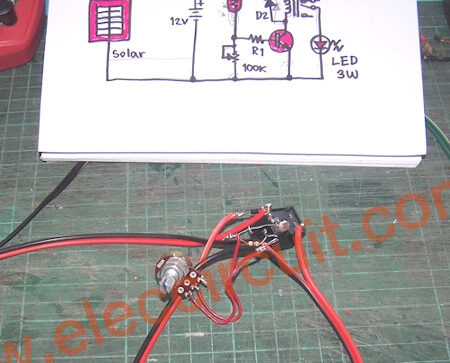
How to build
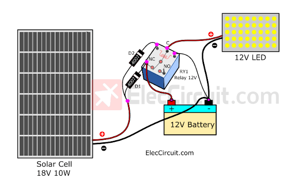
Next, let’s start building. There are just a few components in this circuit. So, we do not need to use the PCB. We can solder the component pins and wire them together to form a complete circuit. Let’s look at the circuit wiring diagram below, which makes it easier for beginners to understand and build this circuit.
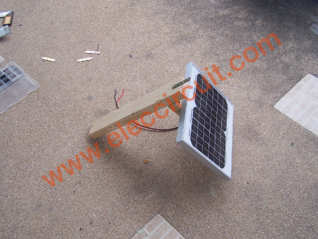
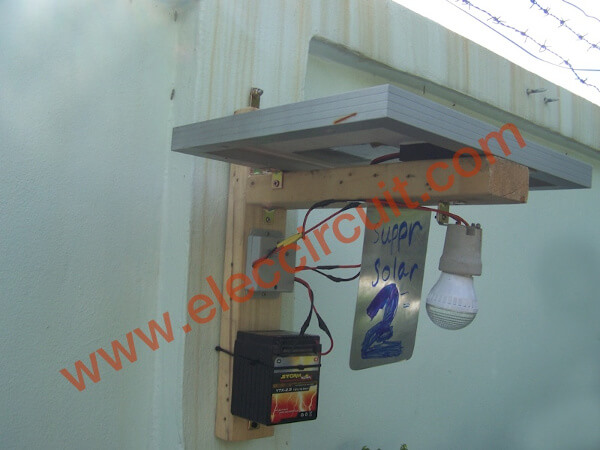
Install the solar cell on the wooden plank and turn it towards the sunlight. Next, install all parts of the circuit under this solar panel.
Connect the circuit to the battery and measure the battery’s voltage.
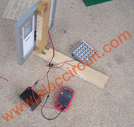
We installed this circuit to actually use it to light up the surrounding area at night.
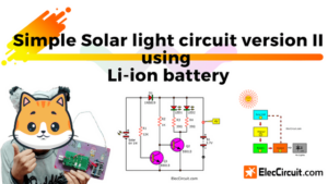
Automatic LED 12V Solar Light Circuit 2
The simple outdoor Solar Lights Circuit (version 1) works quite well. It provides light for about 5 hours from 6:00 p.m. to 10:00 p.m., but it cannot remain on for longer than that.
So, we created this Automatic LED Solar Light 2 (Version 2) to lengthen the lighting time. It also has higher performance. See a comparison between version 1 (left) and version 2 (right).
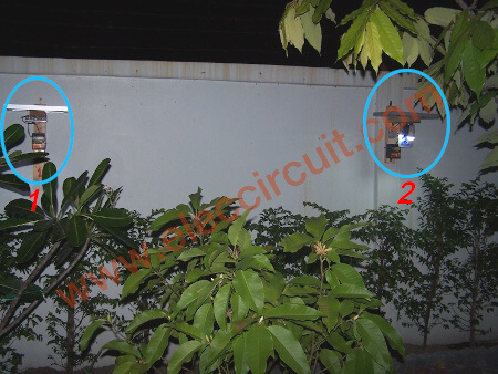
At approximately 10:00 p.m., Version 1 is completely off, but Version 2 is still lit. Both circuits use batteries and solar cells of the same size. How did we improve it? Let’s find out.
Improvement through adding a light detector
The problem of the first circuit may easily be solved by increasing the size of the solar cell to 20W and changing the battery size to 12V 5Ah to keep more current.
But if the battery, solar cell, and LED are the same on both circuits. We would have to find other ways to make the most of our energy.
Its problem is that the LED turns on too early; when there is no power from the solar cell, the circuit turns on immediately. It is better to use a direct light detection circuit and adjust the sensitivity directly. Because usually, in the evening, the time when it gets really dark is 7:00 p.m.
If we always start with what we have, it’s going to be easy. That is why we finally got this Automatic LED Solar Light Version 2 with the quality we needed.
How does it work
We added a simple light detector circuit consisting of LDR1, a transistor (Q1), and resistors (R1, R2, VR1). They work great with the relay we have.
How to charge solar lights with on/off switch?
To make it easier to understand, let’s take a closer look at the working order. As shown in the picture below.
During the daytime
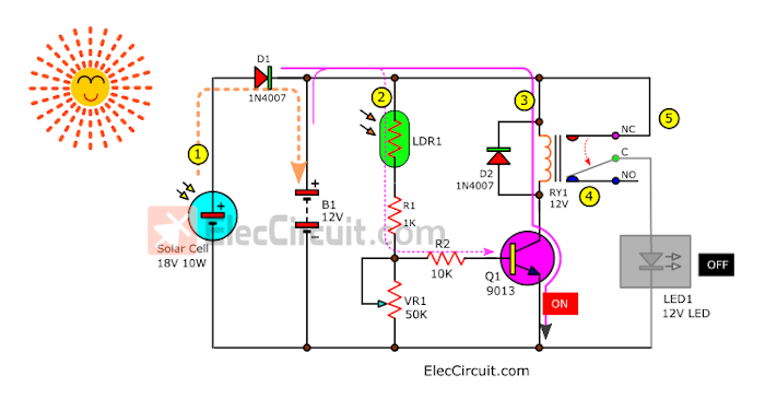
- The solar cell current flows through D1 to continuously charge the battery.
- The LDR1 is a light-dependent resistor (photoresistor). It has very low resistance. So, some current flows through LDR1, R1, and VR1 to the ground. They are all connected in series as a divider voltage circuit. This allows the base current to flow through R2 to B of Q1. Causing Q1 to conduct current or a turn-on state.
- So, the current flows through the RY1 coil through C-E of Q1 to the ground, making it a complete circuit.
- Causing the relay contacts NC and C to be pulled apart, instead becoming NO and C that are touched.
- The current cannot flow through contacts NC and C, so the LED turns off.
At night
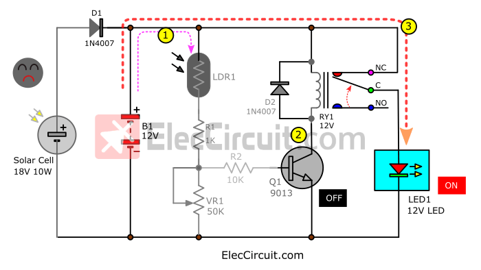
- Now that there is no current from the solar cell, only the current from the battery remains. The resistance of LDR1 is so high that no current can flow through it. Thus, no current will flow through R1, VR1, or R2.
- When there is no R2 current, there is also no base current for Q1. So, Q2 does not conduct current, and no current flows through the relay coil.
- This causes the relay contacts to be released from NO and C to become NC and C. Thus, there is electricity from the battery flowing fully through to the LED lamp.
We added VR1 to adjust the sensitivity of light detection. so that we can adjust how dark or light it is for the LED to turn on.
How to assemble
First, you should prepare all the parts.
Components List
Q1: S9013, 40V 0.5A, TO-92 NPN Transistor, or equivalent
R1: 1K 0.25W Resistors, tolerance: 5%
R2: 10K 0.25W Resistors, tolerance: 5%
VR1: Linear Potentiometer
LDR1: Light sensor 5mm Light Dependent Resistor Photoresistor
RY1: Relay with SPDT 10A min. switch coil voltage 12V. Coil resistance 150-600 Ohms.
D1,D1: 1N4007, 1,000V 1A, Silicon Diode
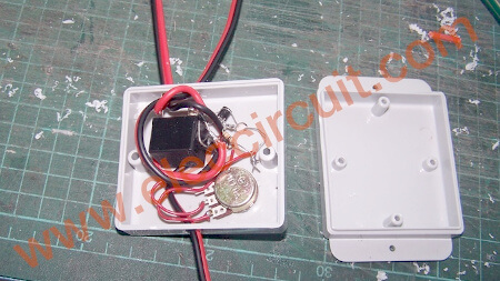
This project has a few components. So we do not use PCBs. See the wiring layout below, as we connect them directly.
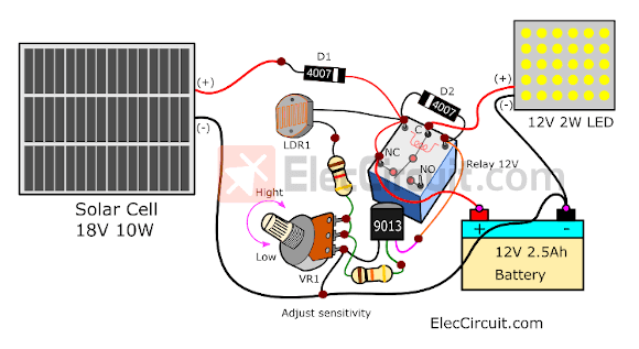
This circuit should be encased in a waterproof plastic box. We drilled holes to pass the wires through to the solar cell, battery, and LED.
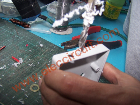
An example of the plastic box that we choose. It can fit the circuit inside it perfectly. And we drill the hole to install the potentiometer so that we can easily adjust the sensitivity.
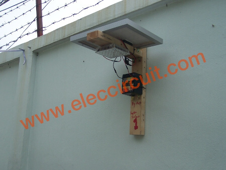
Install this plastic box on the prepared wooden structure. And connects wires to the battery, the solar cell, and the LED.
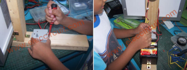
And later, we installed it in our garden. Everyone is happy.
Conclusion
Although these circuits are very simple and have few components, they work well enough. Just like a good tree, we must look at its fruit. These circuits are as well; we have to look at their results.
Get This
All full-size images and PDFs of this post are in this Ebook below. Please support me. 🙂
GET UPDATE VIA EMAIL
I always try to make Electronics Learning Easy.
Related Posts

I love electronics. I have been learning about them through creating simple electronic circuits or small projects. And now I am also having my children do the same. Nevertheless, I hope you found the experiences we shared on this site useful and fulfilling.
Excellent idea. Please keep sharing yours and sons solar ideas with us
Superb.
Hi,
Thanks for your feedback.
Hi Chayapol Well done for such an ingenious design both electronic an mechanical!
The only thing i would point out is that there is no in-line fuse on the battery, so if there was a problem everything would be at the battery’s maximum current potential Eg 100Amps even though at this current the battery voltage would drop significantly.
But looking at it another way as well as a light it would make a nice heater!
Please carry on inventing things i love to see tour things. I was probably about 8 or 9 years old when i started with electronics
Paul
Hi Paul,
Thanks you feedback.
It’s nice Fuse protection battery explosion.
I am also love DIY electronics same you.
Chayapol
I am puzzled why you are using a relay, as this will usually draw more power than the LED, possibly a Mosfet would be drastically more efficient ?
Otherwise, keep up the good work
Hi William,
it is good idea next project i will use mosfet.
thanks
Chayapol
I learned electronics as a child instead of TV and comic books. I am old man now. Still love electronics. Became eng. keep up the good work. English will come to you.
Jim USA
Hi Jim,
I am very happy that hear you sound. I tech my son with Electronics,too. He study with homeschooling.
Great Post!!!!
This is a great project. I want to know that can i use 5 watt or 15 watt solar panel instead of this one without any change in circuit.
Regards,
Faheem
Sir..i want make 1w led solar lantern .ple send me idea..how to create led solar lantern,
Looking for a solar 3W 8.97v 3A CIRCUIT to light it in a temple as already having a solar panel
Hi,
Do you have a Solar cell 3W 8.97v? It’s probably not a good fit for this circuit.
Because a small solar panel for this circuit.
You may experiment with: https://www.eleccircuit.com/solar-light-circuit-2-using-li-ion-batt/
My daughter experimented with it and it worked fine.
Excellent read, I just passed this onto a colleague who was doing a little research on that. And he just bought me lunch because I found it for him smile So let me rephrase that: Thank you for lunch!
Hi,
Thanks for your visit. 🙂