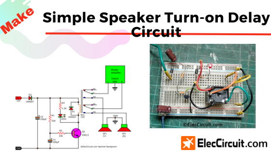
Today we are going to introduce you to a Simple Speaker Turn-on delay Circuit. Imagine after you finish building your own OCL power amplifier circuit.
But every time you turn it on, within the first 3 seconds, you hear a loud “tlub” sound from a speaker.
Wouldn’t you feel annoyed by that sound? Apart from the minor annoyance, this sound is caused by a voltage spike that can damage the speaker.
So let’s find a solution to this problem.
The main idea of the speaker delay circuit
When we turn on a normal OCL power amplifier, at the first instance, the output voltage will swing between positive and negative, as high or as low as the power supply voltage (+24V and -24V). And then gradually decreases until it reaches 0V within 3 seconds.
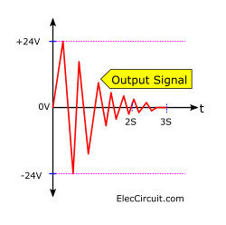
This type of voltage spike has quite a high amplitude, although it only happens in a short time window. It is also considered a DC pulse signal, which can be harmful to the speaker.
Let’s sum up each point of the problem, find the simplest solution to it, and put them all into an easy-to-understand block diagram.
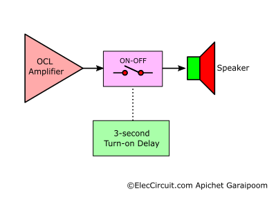
We can solve this problem by using a switch that will disconnect and connect the speaker from the output of the amplifier, as shown in the block diagram above.
In the first instance, after the amplifier turns on, the 3-second Turn-on Delay block will turn the switch off, disconnecting the amplifier and the speaker.
And after three seconds have passed, the 3-second Turn-on Delay block will send out a command to turn on the switch, connecting the amplifier and the speaker as normal.
As a result, the voltage spike in the first few seconds of the amplifier turning on is prevented from reaching the speaker.
Turning It Into Circuit Diagram
Now let’s pick the components we need according to the block diagram above, with the goal of making it as easy and efficient as possible.
The Relay as a Switch
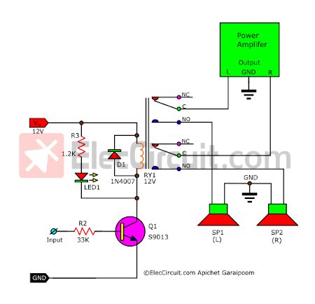
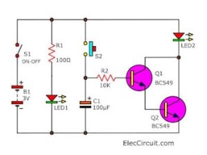
Start with the switch block. We are going to use a 2-contact 12V DC DPDT relay to manage the connection between the stereo output and two speakers. The relay here basically functions as a normal switch, where instead of a physical switch, it is controlled by the voltage applied to its coil.
We picked a 12V one because it is very easy to buy, given how widely used it is.
Normally, the resistance of a relay coil sits in the 160Ω to 600Ω range, depending on the size of the contact pad. In this case, we use 180Ω, which requires a coil current of about 0.067A from I = 12V/180Ω. Hence, we are going to use a 12V 300mA power supply.
We also need a transistor to drive the relay; today we chose the S9013 NPN transistor. It has a maximum IC of 0.5A, which is definitely enough for the relay coil.
Now we put together those components into a simple sketch circuit, as shown below. This transistor circuit is set up in a common emitter form, which has an exceptionally high gain and input impedance.
As a result, it operates with just a small amount of input current.
The circuit will only function when the input is supplied with 12V from the power supply. This base current flows through the input and R3 and goes directly to the B of Q1.
Then the transistor will start working after receiving this forward bias, letting the collector current flow freely through to the relay coil and triggering its contact.
Finding the Value of R2
We have explained the process of calculating the value of R2 (RB) many times already, but it is the basics that should be mastered, so let’s go over it again.
R2 = VR2/IR2
VR2 = Vin-VBE
From Vin = 12V and VBE = 0.7V
Substituting the VR2 = 12V – 0.7V
VR2 = 11.3V
Then, Find IR2, which is the same as the IB of the transistor.
IB = IC/hFE
From IC = 0.067A and hFE = 200
Substituting the IB = 0.067A / 200
IB = 0.000335A
R2 = VR2/IB
Subtituting the R2 = 11.3V/0.000335A
R2 = 33,731Ω
We will use 33K instead.
Also, there should always be a diode (D1) across the relay coil to protect the transistor (Q1) from the high-voltage pulse generated by the relay coil switching off.
While the LED indicates if the relay and the transistor function properly or not. Whereas R3 limits the current for said LED.
The 3-second Timer
Next, we need to find a way to make the transitor circuit remain on for 3 seconds after it turns on. The common way to make a timer circuit like this is to use a capacitor, as they are cheap and easy to put together. So in this case, we will be using them as well.
As you may already know about the basics of capacitors, their normal state is their discharge state. In this state, the resistance within them is quite low, and the voltage drop across them will be zero.
But when it receives an input voltage (Vin) of 12V, the capacitor will enter its charge state. The voltage inside it will gradually increase to match that of the input.
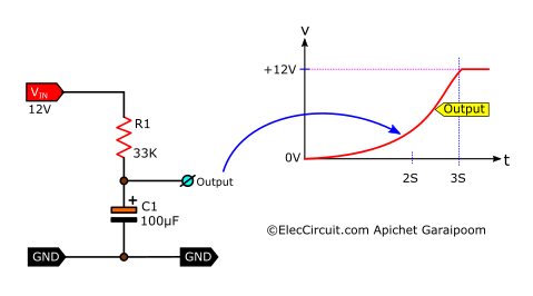
The RC time constant, which is the time that it takes for the voltage to charge a capacitor, can be an essential part of the timer circuit. We figure out the time through the use of this simple formula:
Time Constant (T) = R x C
So if R = 33K (33,000Ω), C=100µF(0.0001F)
Then T = 33,000 x 0.0001 = 3.3s, which is around the three seconds that we need.
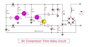
It functioned fairly well when we tried to connect the output of this timer circuit to the input of the transistor circuit from earlier. Adding up to the finished circuit, as shown below.
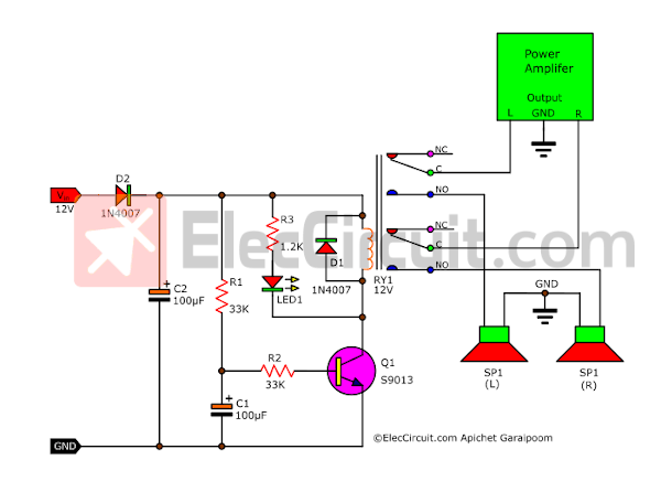
In addition, we also add in C2 to increase the efficiency of the circuit by improving Q1 and D2 to help prevent the inputting of power supplies with the wrong polarity.
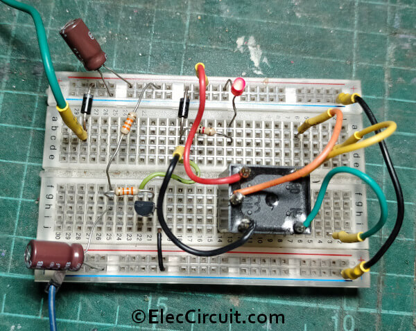
Testing the speaker delay circuit
We then test the speaker delay circuit on the breadboard.
In the case that you cannot find a 2-contact relay, you might be able to substitute it with two 1-contact relays instead. Both relays will have to be connected together in parallel.
Which will lower their coil resistance from approximately 400 ohms each to around 200 ohms combined.
If the circuit shows a sign of error—not working—it might be due to the deterioration of the transistor. It may decrease its hFE value, causing it to not be able to amplify a low current from R2.
If changing the transistor is not plausible for you, you may try to increase the capacitance of C1 to 200uF and decrease the resistance of R2 to 22K.
Or if the three seconds delay is not enough for you, then you can increase it to six seconds by changing C1 to 220uF.
Parts list
- R1, R2: 33K 0.25W Resistors, tolerance: 5%
- R3: 1.2K 0.25W Resistors, tolerance: 5%
- RY1: Relay with DPDT 5A switch, Coil Voltage 12V, Coil resistance 150-600Ω
- C1,C2: 100µF 25V Electrolytic Capacitors
- Q1: S9013 or equivalent, 40V 0.5A, TO-92 NPN Transistor
- D1,D2: 1N4007, 1000V 1A, Silicon Diode
- LED1: Red 3mm LED.
Conclusion
This speaker turn-on delay circuit functions quite well and is suitable for a small OCL amplifier that lacks a speaker protection circuit. This function is normally built into a speaker protection circuit. So does the OTL amplifier circuit; it does not need one.
Anyhow, it is still a good way to learn about a turn-on delay time circuit. These types of circuits can have many other applications, such as an electric motor, a monitor, a heating coil, etc.
Because they can reduce the effect of a short voltage spike that will cause harm to that load.
Look: the loudspeaker protection circuit project

I love electronics. I have been learning about them through creating simple electronic circuits or small projects. And now I am also having my children do the same. Nevertheless, I hope you found the experiences we shared on this site useful and fulfilling.
Need to invert labels IN and GND.
Hi DIRCEU ZANELLA,
Thank for your help. You just edited it.
is there a box already made to hook up 3 ac at once , i have jbl 2 monitors plus the subwoofer, i have to use 2 extenson boxes with a switch, i turnon the sub woofer box and after sub is on, then i turnon the 2 other speakers which are attached to another extension box to do it manually… is there a box already made that i can purchase
Bom dia !
Como seria o turn-on Delay para um som 2.1 ?
Quero dizer :
2 canais Estéreo + 1 canal Subwoofer .
Todos debaixo da mesma fonte de alimentação .
Grato pela atenção .
Good evening.
The main principle is that it cuts speakers. If you have more than 2 speakers, you should probably add a contact relay for each speaker.
Or you should check whether the internal circuit is an OCL amplifier circuit or not.
The relay may be used only for the OCL amplifier or BCL amplifier. For an OTL amplifier, this delay system is not required.
In fact, in the new generation of audio systems, there may already be this function.
Thanks
Does this work when shutting off as well? My sub amp makes no noise when auto-powering on, but thumps the speaker when going into standby, about 5 min after the music stops.
If not, do you have a suggestion for that scenario?
What’s the purpose of C1 and D1?
Hi,
Please read in article again my dad just rewrite it new. 🙂
What relay did you use I cannot energise the relay I am using.12v 5amp what should the coil resistance be.relay not operating.
Regards Steve.
Simple speaker delay circuit.
This circuit will not work.as drawn. This configuration is for a PNP transistor not NPN.The load relay should be connected between the collector and positive rail.The emitter should be connected to ground.This circuit then operates as described
Regards
Steve patten
Hello,
Thank you very much. It has since been corrected.
Hello,
nice work, I want to buy ebook, is it possible to pay via PAYPAL?
Thank You, Jiri
Hello,
I’m glad that you’re interested in supporting us.
But unfortunately, we only operate through the Buy Me a Coffee system, which cannot be paid via Paypal.
Thank you
Thank you for the scheme and explaining of the schematic. Super!
Thanks for your feedback.