In this post, I’m going to show you a simple transistor intercom circuit. Imagine your home is large or many stairs. You need to call your kids. But you are busy cooking. Is it is nice if you can easily communicate with each other via the intercom?
Even now we have mobile. But what are you? Electronics inventor.
Create your value. Make your free time valuable. By creating this project.
Recommended: Learn transistor works here
Sure, do not hope to see a hard circuit from me.
This circuit has normal parts only. So easy to build and cheaper than IC. At times, you have may them in your stores.
And, they are perfect for a small home
It helped we can contact together easily without a walk or shouting loudly until may have a sore throat.
Want to know more now?
Look:
How it works
In the circuit, you will see three transistors and a few other parts only. They serve as both a receiver and a transmitter together.
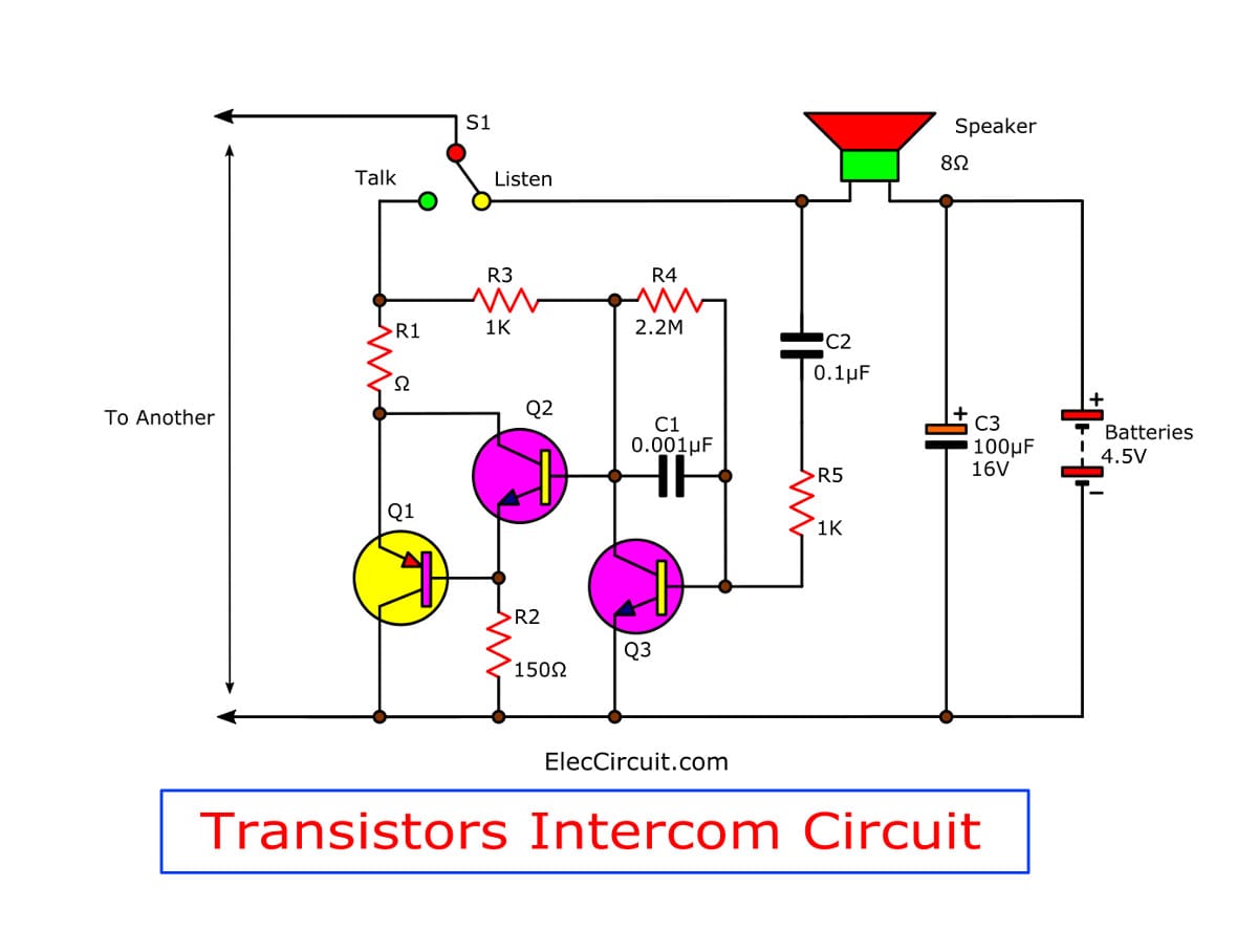
Figure 1: Simple intercom circuit using tree transistors
You may doubt how they work. Let me explain you.
First of all, you need to have 2 circuits and connect them together.
Look at a Block diagram below.
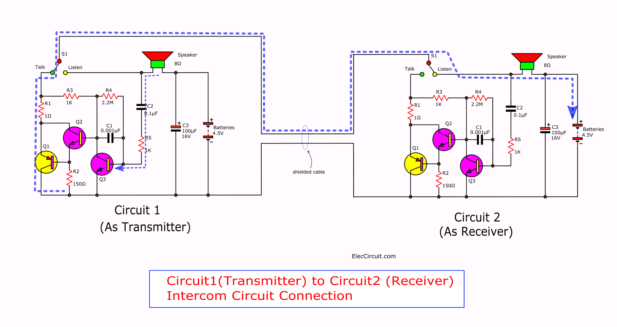
Suppose that we want circuit 1 is a transmitter first. Press S1 to talk. Which, it determines the circuit 1 to works as the transmitter.
That loudspeaker(8 ohms) will be a microphone. We speak into it. To send a voice signal to the circuit. Its coil inside causes an oscillation to generate a tiny signal wave come out.
The 4.5-volts battery is connected that does not affect anything with the speaker or the circuit. Because it is DC voltage, which the DC volts will is blocked by a capacitors-C2.
The AC signal from the speaker comes to C2 and resistors-R5.
Then, enter the base of Q3.
Which both transistors Q3 and Q2 act as a high gain amplifier circuit.
Next, they will send a signal to drive Q1, to control current that flow from the Intercom another one.
And will flow also through the speaker of that receiver intercom( circuit 2). The speaker will also emit the sound signal.
The 4.5-volts battery of the receiver circuit(circuit2) is a power supply of transmitter circuit and a speaker that connected wire together only.
Change talk to Listen
If you do not understand. I explain the confusion. You try to write the intercom circuit another one, connected to the same circuit.
But change position switch-S1 of circuit 1 is a “listen” position. And change circuit 2, S1 to “talk”.
The work will alternate with the above.
Look:
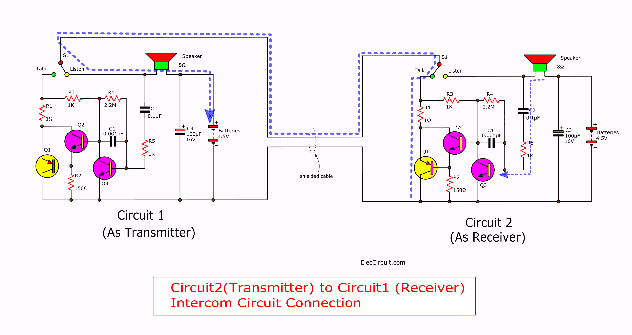
You will better understanding.
The frequency operation of this circuit is designed for frequency range, on the sound speak of human, in between around 200 Hz up to 3 kHz
You may also like these:
Building and application
Before building this project. You need to understand that it has less sound. But enough for a quiet home.
This project uses a few parts so can assemble on the Perforated board.
Or you can make a PCB layout(actual size). Then, the wiring and various components can view of the example in Figure 3 is the component layout on the PCB.
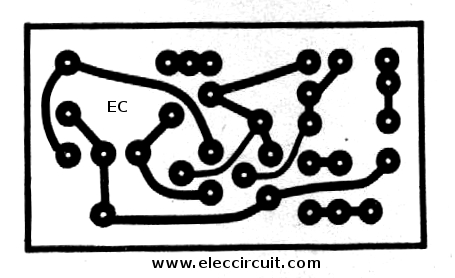
Figure 2 Actual-size,Single-sided PCB layout
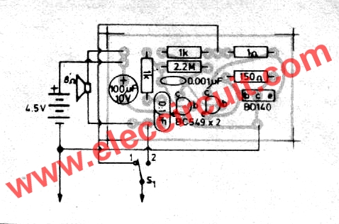
Figure 3 Component layout for the PCB
In the assemble this circuit. You should start with the lowest first. To look beautiful and easy to build. Start from resistors and sort of high continuously.
For the devices have various polarity. You should be careful in the assembly circuit.
Before placing these components will set the polarity at PCB and the part match together.
Because If you put backward, may cause equipment or circuit damage.
How to check polarity and input device.
The soldering iron is less than 40watts. And Use of lead solder containing lead and tin in the ratio of 60/40. Including the need also to have a flux inside the lead.
If the wiring between the receiver and the transmitter very far. And measure the resistance of both wires about 0.25 ohms.
You can also add voltage of 6-volts battery and D sized battery will cause can use longer time than the AA-sized battery.
Or if you want to save energy using a 1.5 volts battery 2 PCS. It still works.
The components list
C1: 0.001uF 50V Ceramic or Mylar
C2: 0.1uF 50V Ceramic or Mylar
C3: 100uF 16V, Electrolytic
Q1: BD140, 80V 1.5A PNP Transistor
Q2, Q3: BC549, 45V 100mA NPN Transistor
0.25W or 0.5W Resistor, 5% tolerance
R1: 1 ohms
R2: 150 ohms
R3, R5: 1K
R4: 2.2M
The switch; single pole double throw (SPDT) (3 poles two strokes.)
The wires, Speaker 8 ohms 0.25 watts, Battery with a battery carrier
Note:
Remember to buy two sets for the second machine to complete.
GET UPDATE VIA EMAIL
I always try to make Electronics Learning Easy.
Related Posts

I love electronics. I have been learning about them through creating simple electronic circuits or small projects. And now I am also having my children do the same. Nevertheless, I hope you found the experiences we shared on this site useful and fulfilling.
i need equivalent full circuit of “simple intercom using tree transistor”
Is it possible to increase the amplification by changing values of some resistors?
Hi blaise yuo-b,
Thanks for your feedback.
Here is full circuit, but it old.
Hi Chris
Thanks for your feedback.
Yes, you can increase sound with changing the resistors.
But it not well because it low voltage supply.
pls sir, the two wires going to the others,where exactly am I going to connect it in the other circuit
and also, ½w resistors are not available in my place. can I use ¼w instead? and what’s the effect
how does the speaker work as a microphone ?
and if I actually want to add a microphone what can I change ?
Hi,
When we speak to a speaker. It can generate a tiny signal like a dynamic microphone.
This circuit is weak sound. Please look at other: https://www.eleccircuit.com/mini-intercom-by-one-ic-op-amp/
But it use IC and use a lot components.
Is there any buzzer option during calling?
Hello Gautam,
Thanks for your interest in this circuit.It is possible.
Unfortunately, I’m busy. So, cannot test the circuit as you want.
What is the size of the PCB???