This is a simple op-amp IC tester circuit. You can use them to fast check the many op-amps IC good with blinking LED circuit. It has a few parts so cheap and easy to build.
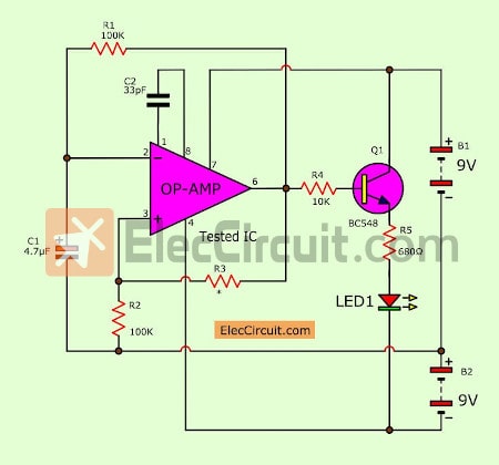
The figure below is the schematic diagram of this tool.
How Op-amp tester works
In normal we put a good op-amp into the circuit. They will generate a low frequency in the square wave. Then, feed the power supply (two 9V battery). Next, there is DC pulse comes out of pin 6 in all-time.
Which using the charge and discharge of C1 in generating the frequency of about 1 Hz. (Calculated from ½ R1, C1).
Next, both resistors R2 and R3 act as setting the reference voltage, 4.5V. To compare the positive pin and negative pin of the op-amp IC.
After that, the capacitor C2 at pin 1 and pin 8 offset a loss frequency of IC. This frequency is bias voltage to pin B of Q1. Which there are R4 limits a safe current into B pin.
When the positive frequency voltage is into the lead B of Q1. It will cause Q1 started working. Then, the current flows through the lead C to E. And, it flows through LED1 to the negative supply. So LED1 is lit up.
But sometimes the output is a negative voltage instead. So Q1 will stop immediately. Because of Q1 as compared to the reverse bias.
The LED1 alternately flash ON and OFF about once per second like this. Until the positive frequency will come.
Therefore, It indicates us this op-amp is good.
But if LED1 show is different this. It indicates that the IC may be destroyed.
In the figure below will show connections between devices together.
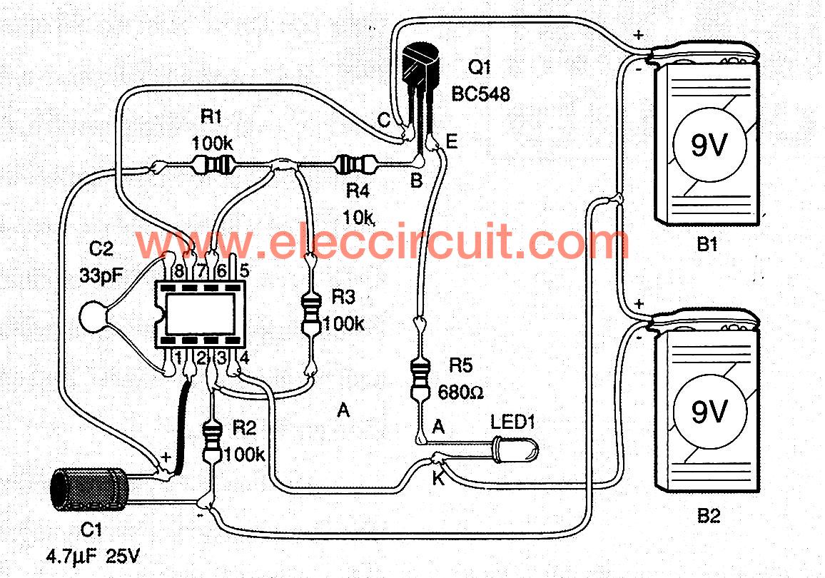
Figure 2
The parts you will need
Resistors ¼ W +-5%
R1-R3: 100K (Brown, black, yellow, gold)
R4: 10K (brown, black, orange, gold)
R5: 680 ohms (Blue, gray, brown, gold)
Capacitors
C1: 4.7uF 25V ( Electrolytic)
C2: 33pF 50V (Ceramic)
Semiconductors
Q1: BC548, 45V 100mA NPN Transistor
LED1: 5mm LED color you want
Normal Parts
Socket IC 8 pins
A 9V battery with snap connector
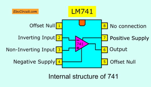
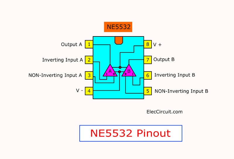
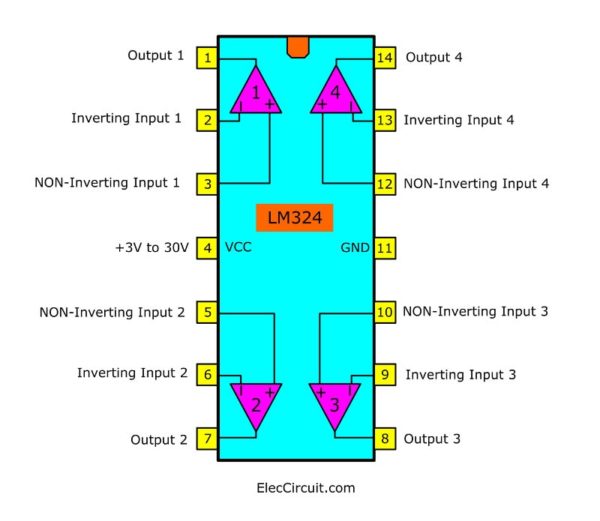
What is the number of OP-AMP?
You can use it check OP-AMP. But you need to check the pinout of each OP-AMP number.
For example:
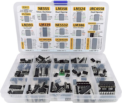
Do you have these ICs yet?
GET UPDATE VIA EMAIL
I always try to make Electronics Learning Easy.
Related Posts


I love electronics. I have been learning about them through creating simple electronic circuits or small projects. And now I am also having my children do the same. Nevertheless, I hope you found the experiences we shared on this site useful and fulfilling.
Thank You Very Much.
schematics for FM radio schematics
Thank you Admin. for the circuit diagram of DC to DC step-up converter using IC-TDA2004. I hope someday I could make it when I return to my home country-Philippines, as of now I’m working here in KSA. Keep up the good work!!! eleccircuit.com
If i use BC558 instead of BC548, should i change some thing?
Thank You Very Much.
I would like to build these “Digital Integrated Circuit Tester”, but i don’t know where can i order these. And i’d like to test and know what is Bad and Good IC chip. hope you could help me. lot of many thanks.
What types of op-amp ic ?
Please read the text.