You are looking for many power supply circuit diagrams, right? Because the various electronic projects need to use them as an energy source.
These listings below may help you choose the type to match your usage, also most of them are cheap and easy to build. But most important is the ideas you could get out of them.
3 Power Source for Electronic Devices
Let’s look at the three most used types of Power Supplies.
Types 1# Battery—A lot of circuits use a little power. So, it can be powered by batteries. The battery is small and easy to use anywhere. But normally they are low voltage. Thus, they are best used for low current loads. But for a heavier load, what should we do? Rechargeable batteries are a better answer. Can be reused many times to save a lot of money.
Type 2# Solar—We can use the solar cell to power our circuit directly. But usually, we like to use it as a battery charger for a rechargeable battery. For example, a battery charger inside a solar light, etc.
Type 3# AC Line—Often through an AC Adapter as a power supply. They are more compact and easy to use than the battery. We can adjust its output to various voltages and currents. At home, we should use them instead of batteries and solar. Because it will save our money replacing our batteries when it is dead and convenient, no need to wait for sunlight when using a solar cell.
Power Supply circuit Expalintion
If you are a beginner, I know that you do not want to waste time learning principles, and want to create a power supply circuit quickly. But you should learn its working principles at least once. To reduce mistakes and select the circuit appropriately for your usage. It will make your life easier.
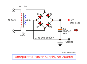
Unregulated Power Supply Circuit
Almost all circuits are based on this principle. So, you should read it beforehand.
How does Fixed Voltage Regulator work
Even though we do not like complexity. But every project needs good stability. So, this is necessary!
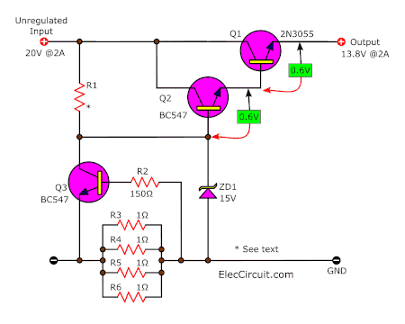
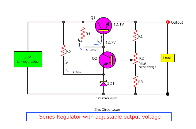
Series voltage regulator circuit diagram with overload protection
Let’s learn about the transistor series voltage regulator with short circuits and overload protection. And how it reduces ripple. LEARN MORE
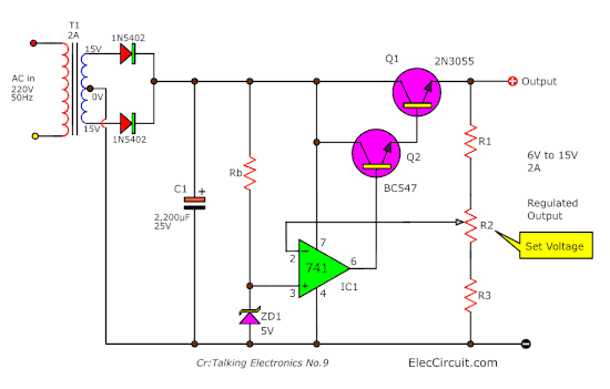
How does a voltage regulator using OP-AMP work
Learn an error voltage sensor using transistors circuit work inside of variable voltage regulator using 741 and 2N3055.
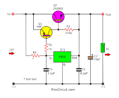
Current booster circuit for 7805
Learn how to increase/boost up current of 7805 (or 78xx) regulators with helping the 2N3055 and others transistors.
Still curious? Click here to find out: Basic AC-DC Power Supplies
Top 8 power supply circuits
On our site have a lot of power supply circuits. We can not show it all to you. Thus, for saving you time see the lists below.
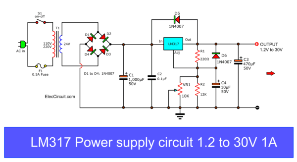
LM317 Variable DC Power Supply
You can adjust an output voltage from 1.25V to 30V at 1.5A. I like this one. Because… It is easy and cheap. For example, You can use it instead of a 1.5V battery. READ MORE
Read also: LM317 pinout and how to use, Calculator Datasheet
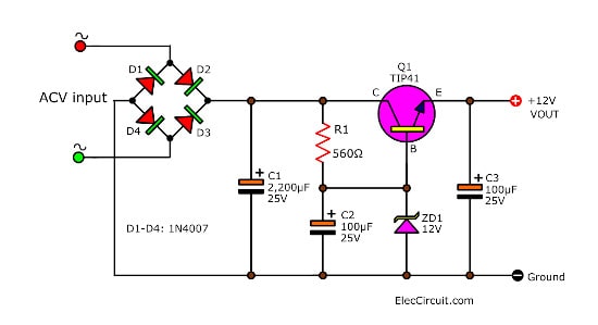
Simple Fixed voltage DC regulator
We often found this circuit in many appliances. They are quite old circuits but still have many uses. It is very simple with just one transistor, Zener diode, and resistor. The output voltage depends on the Zener diode. Read More
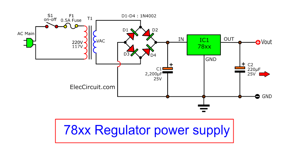
78xx voltage regulator circuits
78xx is a popular 1A fixed DC Regulator. Because of easy to use and cheap. And the output depends on the IC. If you need a 6V 1A output for a digital circuit, then the LM7806 is your pick. READ MORE
Also Learn: 7805 voltage regulator circuit, pinout, and more
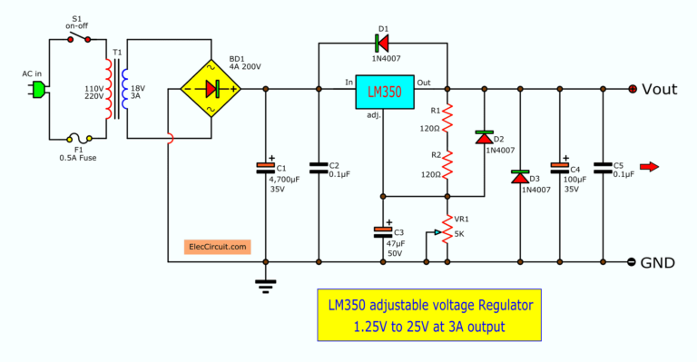
LM350 Adjustable Regulator circuit
I sometimes need to use 3A variable voltage source. But… LM317 cannot help me, easily. In a short time, we used the LM350 Variable regulator. It is the best linear IC@3A. The output is 1.25V to 25V. READ MORE
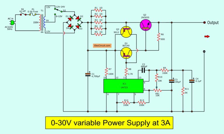
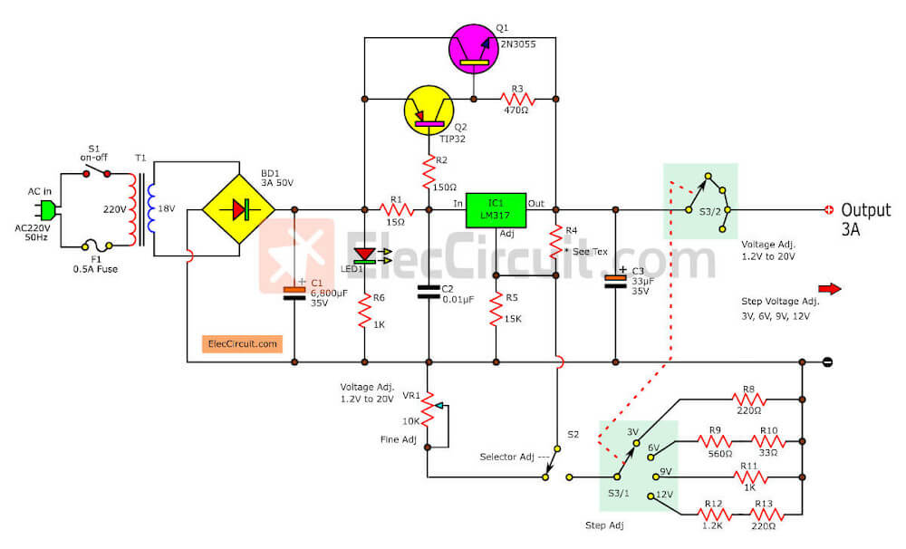
0-30V Variable Power Supply Circuit at 3A
We seldom use 3A Current that can adjust 0V to 30V output. This is a better choice. It uses LM723 as the famous regulator IC and Power transistor, TIP3055. READ MORE
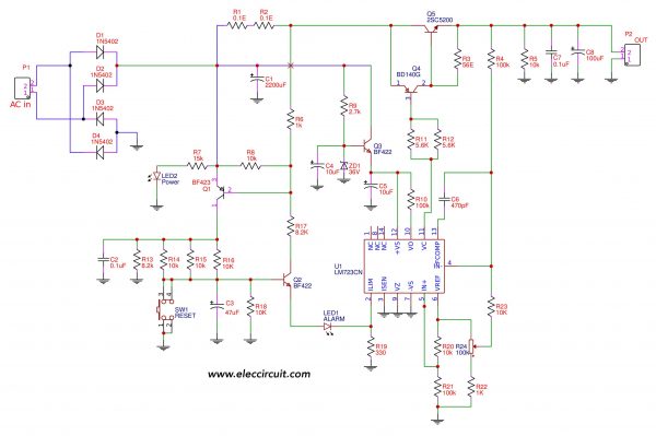
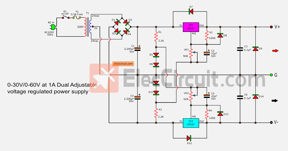
If you need to use the output voltage over 30V or adjustable from 0V to 50V. It has a key component of LM723 but for the higher voltage, the 2SC5200 transistor is also needed. With full overload protection. READ MORE
Build 12V 2A power supply with a hammer
If you hurry up and have no PCB. This idea may good. You can build a 12V 2A adapter easily and cheaply. By using a hammer and snail on the wood board. Learn more
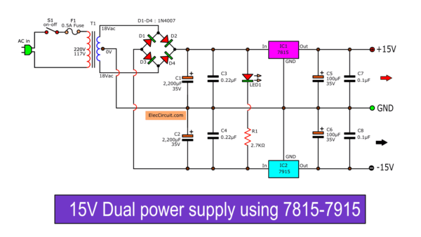
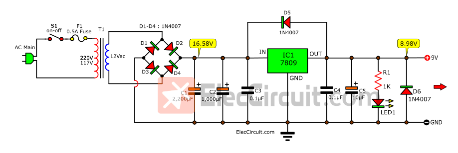
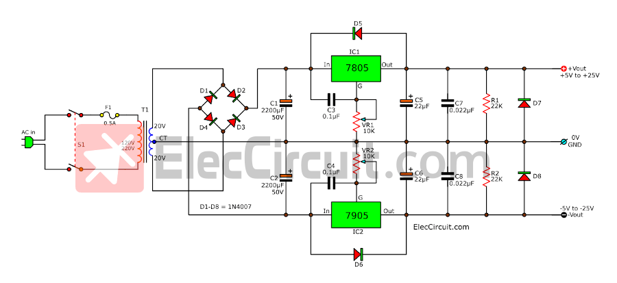
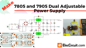
15V Dual Power Supply circuits
If you need to use many circuits using OP-AMP. For example, Preamplifier with tone control and more. They need to use +/- 15V regulated supply. We have 3 circuits using 7815-7915 and transistors. READ MORE
Other Linear Power Supply Circuit Diagram
Fixed Volts regulator
Let’s look at fixed-voltage regulator circuits at various voltage levels. To provide an idea for choosing a variety of uses.

Using 7805 chip and recycling electronic circuit boards
For any circuit requires a stable power supply, low noise, and safety from AC high voltage leakage.
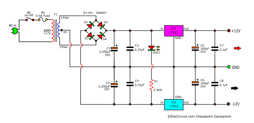
12V Dual Power Supply using 7812, 7912
This circuit is suitable for a preamplifier tone control with an OP-AMP circuit.
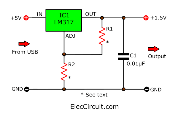
Converts USB to 1.5V or 3V or 2V output!
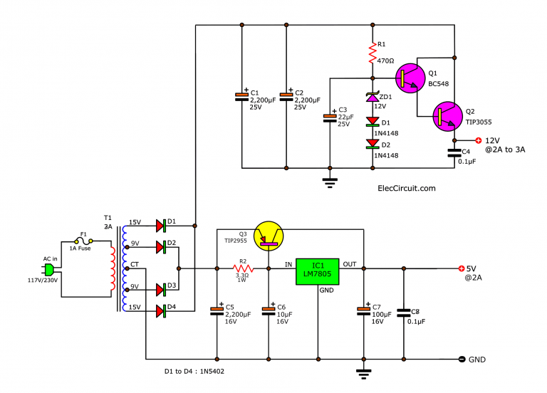
Many ideas of 12V and 5V Dual Power SupplyCircuit Diagram at 3A max
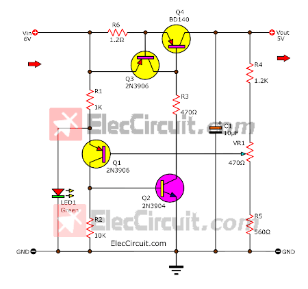
Make a 5V low dropout regulator circuit using a transistor and LED lowest voltage input is 6V so across it is 1V only, making output is 5V 0.5A
Transformerless power supply circuits
We often do small projects, that require a small power supply. But the normal transformer is big and heavy. We will learn about these transformerless power supply circuits. So you can select as you want.

18V Pre-amplifier DC regulator circuit
This circuit is suitable for transistor pre-amplifier circuits, improving your sound system. Because of low noise. Read more
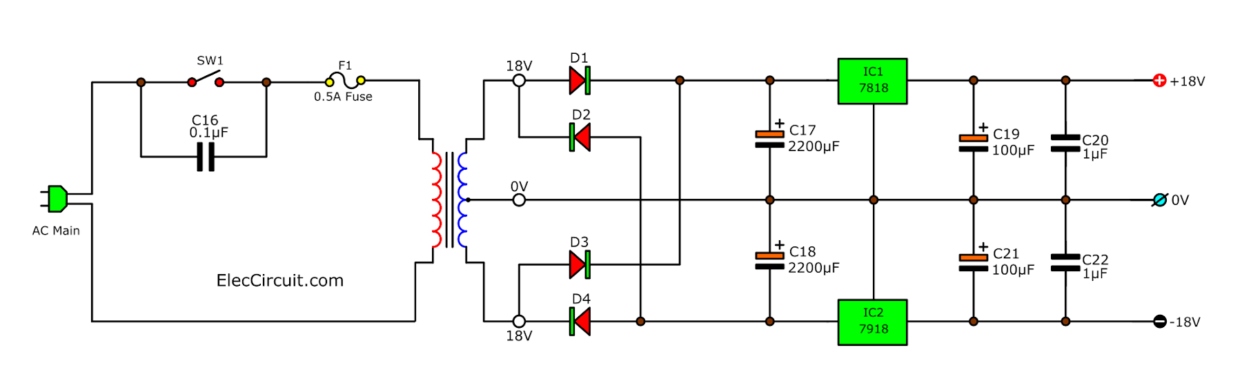
Some circuit requires an 18V dual power supply circuit or 3 terminal outputs (+18V, – 18V and Ground). We can use IC7818 and IC7918 to do this power supply.
Other circuit list
- Digital DC Regulator If you are looking for a 5V power supply for the digital circuit. But you have a 12V source and battery. I will show you, a 12V to 5V converter step-down regulator. In many ways for using, it depends on the parts you have and other suitability. Recommend
- 5V 5A, Top Linear Regulator
- Small Uninterruptible UPS
- A lot of 6V supply diagrams
- 12V to 6V Converter circuits —Your load is too hot. It will be damaged. Why? You connect it to a 12V battery. It can get 6V only. If you do not want this to you. You should read 10 ways to make a 12v to 6v step-down circuit.
- 9 volts 2 Amps DC Converter
- Experiment Variable Zener diode
- Negative Voltage Regulator using PNP Emitter Follower
- 24V 2A supply circuit Diagram
Adjustable Power Supply Circuit
Start with: Variable power supply circuits list

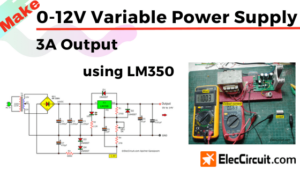
0-12V 3A Variable Power Supply Circuits
In a normal circuit, the general LM350 regulator has a start voltage of 1.25V. But this circuit is special that start of 0-volts. We use only one IC and a few other components. So cheap and easy for you. Read more
LM317 with pass 2N3055 transistor circuit regulators
- 12 volts,13.8V High Current 30A,25A,20A,15A for HAM Radio DC [Easy but well]
- 0-30V, 5A DC Adjustable Regulator using IC-723, 2N3055x2
- Many Amplifier power supply circuits
- 10A, DC Supply FIX Regulated by IC-78XX and MJ15004
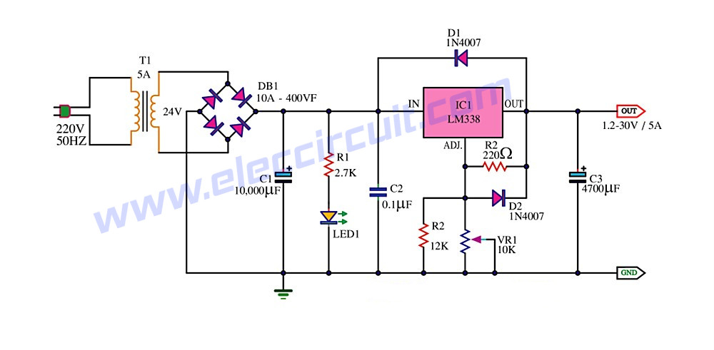
- 0-30V 20A, High current variable regulator using LM338
High volts
- 0-300V, high voltage variable
- How to make a 1.5V to 220V inverter
- Many high-volt power supply circuit ideas
Constant current Source circuits
- Many Constant current source circuits
- Constant current circuit using transistors
- 7805 Current constant for the battery charger
- Voltage Reference using LM334
Why should we use a linear power supply?
There are many kinds of power supply circuits. But they can all be put into two groups.
- Linear Power supply
- Switching mode power supply
How does the linear power supply work?
The AC voltage that goes through a power transformer will be raised or lower depending on the type of the transformer, and then converted to DC voltage. Next, the voltage will go through the regulator circuit system to keep the voltage and current stable for a load.
The explanation above is oversimplified if you want in-depth information. Click here
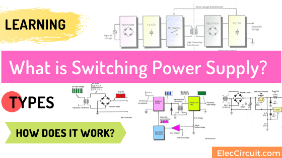
How does the Switch-Mode Power Supply work
It does not contain a big-size transformer instead it directly converts the AC power into a DC voltage. Then, this DC voltage is converted back into an AC signal with a higher frequency than before.
And, the regulator circuit inside will produce DC voltage and current as desired.
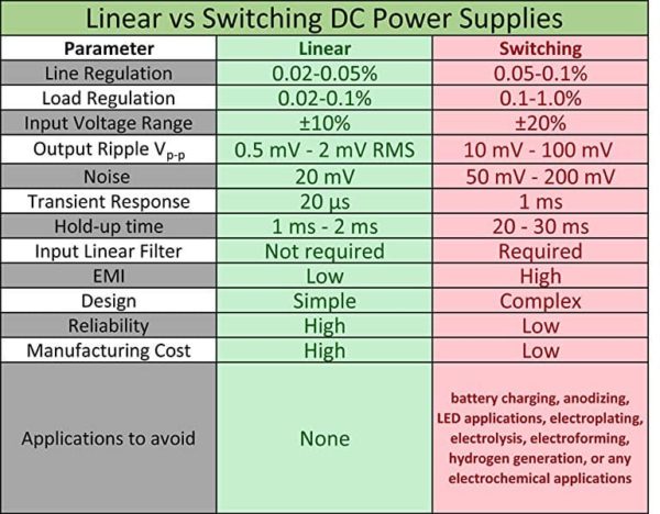
The difference between linear and switch-mode power supply
The table below compares various parameters of linear and switching forms.
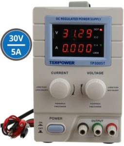
Thanks: Tekpower 30V 5A Supply
I love the linear power supply. Why?
They are:
- Easy to understand a circuit diagram
- Quiet
- High stable, durable and heavy-duty
- Low noise, ripple, delay, and EMI
The switching type is all but just the opposite.
UPDATE: But now I also love it. Because it is better than the linear for its higher efficiency, cheaper, smaller, etc. Causing it to be more popular than before. You may love it with me.
Switching Mode Power Supply circuits
They have a small size and are cheaper than the linear version.
Learn more:
A particular DC switching power supply is very useful. The list below is idea to build a great power supply that is small and saves money. For application or learning.
So, I collect these circuits for ease of accessing the projects that I am interested in. Also, they may be useful for you, too.
Switching Mode regulator
DC to DC converter
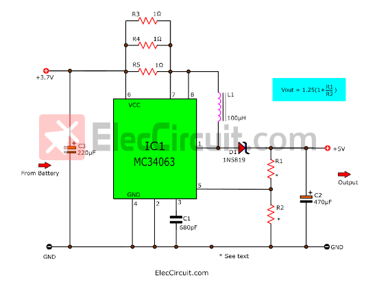
3.7V to 5V Boost converter circuit
Here is 3.7V to 5V boost converter or step up switching circuit using MC34063 and a few parts,1N5819,100uH. For 200mA-300mA of load current.
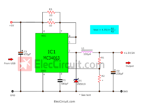
3V | 1.5V Switching Regulator circuit
It is a 1.5V Step down Switching regulator using KA34063/MC34063. Imagine you have an old MP3 player it needs a 1.5V battery.
- USB 5V to 12V DC-DC Step-Up Converter circuit
- Switching Regulator 12V 3A using LM2576-12
- LM2678 – 3.3V, 12V, 5V 5A Switching fixed voltage regulator
- MC34063 Stable battery switching regulator
- LED driver low power using switching Mode
- LM2596 circuit voltage regulator and LM2673 datasheet
- LM2577 Boost Converter circuit | Step up | Datasheet | Pinout
- DC converter 5 volts to +12 volts or high volt than +12 volts
GET UPDATE VIA EMAIL
I always try to make Electronics Learning Easy.
Related Posts

I love electronics. I have been learning about them through creating simple electronic circuits or small projects. And now I am also having my children do the same. Nevertheless, I hope you found the experiences we shared on this site useful and fulfilling.
Thanks a lot for the information
I am lost, I need 1.5 volt battery P.S to light two 1.5 v miniature lights for my Buddy L trucks.The lights I have are 1.5 v, .3 amp. these could be wrong. Is there a better choice. HELP ?
PS, USB 5vto 1.5v step down converter circuit, I think this one will work, I require 1.5 v battery source PS to light two 1.5 v miniature lights for my Buddy L. Do I purchase everything from you how does it work ?
I am lost, I am looking for the diagram of stabilized power EURO CB 1022 if anyone can help me it would be great.
Hi Eric,
Thanks for your question. If I can you. I will be so happy.
Do you want a power supply? How many of the voltage and current do you want?
i MADE A MISTAKE PLEASE READ 2022 and not 1022
I need the diagram of this power supply to repait my unit. This power supply is formy TX/RX radio, i need 13.8 volts 20 Amps, According advertisement i have bought a new one (Nissei PS30SWII) quite cheap 95€, but I want to get the old one repaired and to use in in my workshop.
Eric
hello sir,
i have to make an led strip driver of 12v 5amps 60w please help me to make it with smps transformer
please help me
Hello alok kumar singh,
I do not yet have such circuits. 12V 5A using SMPS transformer. But You may try this: I like it because it is easy.
https://www.eleccircuit.com/simple-designing-12v-5a-linear-power-supply/
I am sorry. If my suggestions can’t help you.
sir how to connect VR1 in variable power supply
Hello, Muhammad Aqib Ali
Excuse me.
Which the circuit do you want to build?
Hello, I own an internet tower and I want a multi-volt electronic circuit to be an alternative to the inverter and use transformers. I want an electronic circuit to convert from 12 volts to fixed multiple voltages 9v, 12v and 24v and the main voltage source is the use of a battery
Hello Hussain,
I glad that you are interested in these circuits. You should probably use a DC to DC converter as a Switching mode power supply circuit. I’m also interested in learning about this kind of circuit. In the future, I will publish it on the web.
Ah… What is the current size of the load? If the load uses less current We choose a simpler circuit. and smaller.
Thanks
i need know how can i create power supply 10 voltage with 5 amp
I’m always burning the potentiometer.help me in lm317 .I use the transformers of 220 ac/24ac . And it keep burning.my connection it right according the schematic I use just like in the example this
Hi,
The maximum input voltage for the LM317 is 40V. Yes, you can use 24VAC transformer. When it changes DC voltage, the voltage level must not exceed 40V. In my experience, transformers with voltages that are too high. Until the problem mentioned in the article occurred.
https://www.eleccircuit.com/lm317-power-supply/#Apply_the_transformer
You may encounter the same problem as me, or in another case, you may encounter a low-quality LM317 that cannot handle voltages as high as 35V. I used to use an LM317 that couldn’t handle voltages above 30V. It would get very hot.