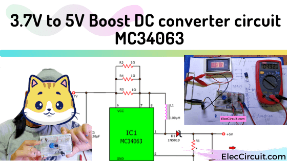
From the previous circuit, I received an email from our friend, he wants the 3.7V to 5V boost converter circuit. It’s very interesting! Let’s test it with MC34063.
We have many ways to do it. I found a lot of cheap ready-made modules on the internet.
Thus, it is not worth building this circuit at all. Because we have to pay more and waste time trying it.
But my daughter said It is fun trying to build it yourself, understand the working principle, can apply it. Sometimes we can even reuse old devices. She likes to dismantle. I think she is right, and you?
How to increase a voltage from 3.7V to 5V?
We know that the boost switching regulator circuit, Some called a step-up DC converter. It will get a low voltage supplied to it, then deliver a high output voltage. At the same time, the output current always is lower than the input current.
How it works
Let’s first understand the simple principle. A boost DC converter is one of the switching regulators.
Look basic block diagram.
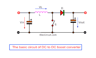
Its internal has a high-frequency oscillator that turns a transistor on and off, they work like a switch (S). Then, they deliver bursts of energy to an inductor (L). Next, the energy from the inductor (L) is stored in a capacitor (Cout) through a high-speed Schottky diode(D).
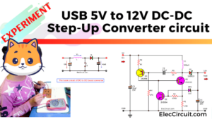
We have already learned or tried to build this circuit in the transistors version: USB 5V to 12V Boost Converter circuit.
Although easy to find devices. But we use a lot of parts. So it’s quite difficult. An IC makes life easier.
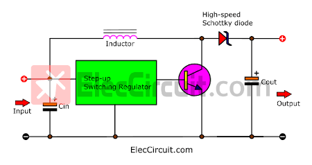
Look above: Basic block diagram of boost switching regulator using IC.
From what we want a low voltage supplied is 3.7V. We look at MC34063A, MC33063A, SC34063A, SC33063A, NCV33063A Datatasheet. It can be lower input is 3V. Thus, we can use it.
Let’s try MC34063 as a Boost switching regulator.
First of all, let’s look at the datasheet. Most of the time, I’ll just look at the example circuit. And then modify or test it according to the components I have. Until the goal is achieved. If it can supply the voltage of 5V at 200mA. I’m satisfied.
12V to 28V Boost DC converter circuit
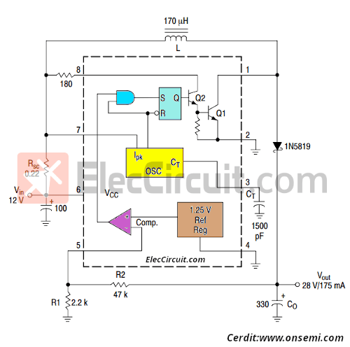
Secondly, เรามี example of the 12V to 28V boost switching regulator circuit. Even it will supply an output of 28V at 170mA. But it is easy until we can modify it quickly.
Internal the chip has an interesting part:
- High-frequency oscillator and transistor to switch on and off as mentioned above.
- 1.25V Ref Reg (reference voltage) and Comp(comparator) Thus, it can adjust and keep a constant output voltage.
Thirdly, let’s try our circuit.
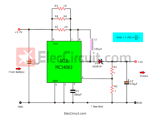
Look at this circuit below, has few details. Because all the complicated details are contained in IC1. See the circuit diagram.
Components choosing guidelines
From the example circuit above. We try to adjust/change equipment as available and we are interested as follows
R1&R2: set the output voltage.
The output voltage is determined by feedback resistors(R1 and R2) from the output to pin 5 (Comparator inverting input). We can calculate Vout as follows:
Vout = 1.25(1+R1/R2)
A typical digital circuit requires a 5V power supply with a tolerance of +/- 5% or 4.75V to 5.25V. So we can choose R1, and R2 according to the table.
| Voltage Output | R1 | R2 |
|---|---|---|
| 4.79 V | 680Ω | 240Ω |
| 5.04 V | 1K | 330Ω |
| 5.05V | 820Ω | 270Ω |
| 5.10V | 1.2K | 390Ω |
| 5.11V | 680Ω | 220Ω |
| 5.14V | 560Ω | 180Ω |
| 5.17V | 470Ω | 150Ω |
| 5.24V | 1.5K | 470Ω |
| 5.30V | 1.2K | 390Ω |
D1: High-speed Schottky Diode
This circuit operates at a very high frequency. Approximately no more than 100KHz. Therefore, use High-speed Schottky Diode. We pick 1N5819 as Schottky Rectifier, 40 V, 1 A because cheap and most popular.
Note:
Some people ask me if I can use 1N4007 instead? I have tried the result is like this. When the load is connected, the voltage drops to approx 3.4V only. Because it is a low-frequency diode. Others hand, 1N4007 can run in the buck-switching regulator circuit.
L1: Inductor
Yes, It is an important component in all switching regulator circuits. In the datasheet, it states 170μH, 220μH, and 100μH.
You could try creating it yourself as we do. But should withstand currents higher than 200mA.
CT: Capacitor
It determines the frequency within the Chip. Without it, the output voltage is approximately lower than the input. We tested 680pF to 0.01μF with similar results.
RSC: Resistors
In the example circuit is 0.22Ω. But we don’t have one.
As we know that when putting three equal-value resistors in parallel, we divide the total resistance by three. We have a lot of 1Ω resistors, so we put three in parallel. Total resistance is now 0.33Ω.
R-180Ω at pin 8, We remove it, then connect directly to RSC.
Cin: Capacitor
An example, circuit is 100μF. We can use it up to 470μF. The result is the same. What value should We choose? Of course, choose a lower value first. Because it is economical and small.
Cout: Capacitor
It affects an output voltage level with the load. The voltage will be lower. However, we try to put capacitor of 220μF to 470μF at 200mA of load current, also the results are similar.
Read also: How to increase more current for 34063 chip 5V 2A buck converter
The components list
Resistors 0.25W
R1: 100Ω *see table
R2: 330Ω *see table
R3-R5: 1Ω
Ceramic Capacitor
C1: 680pF 50V
Electrolytic Capacitors
C2: 220μF-470μF 25V
C3: 100μF-220μF 16V
Semiconductor
D1: 1N5819, 1A, 40V Schottky rectifier Diode
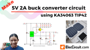
IC1: KA34063 or MC34063, 1.5-A Peak Boost/Buck/Inverting Switching Regulators
Others
L1: 100μH to 220μH at 200mA min inductor
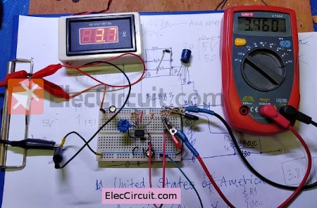
The Circuit experiment
To confirm that it works normally, let’s test the circuit. We assemble the circuit onto the breadboard as shown below.
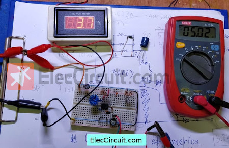
Measures voltage 5V according to the calculation. It is good!
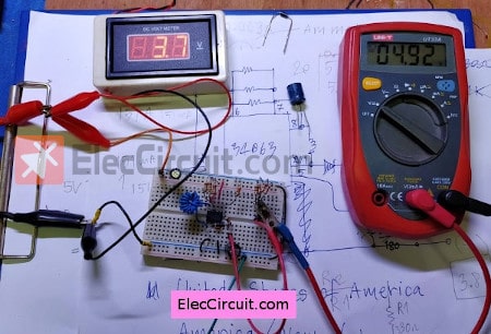
Then, add a load to the output. We want 200 mA of current. Thus, we need to load 25 ohms to test it. Look at 4 x 100Ω resistors connected in parallel. It works! the output voltage is 4.92V.
What’s more, my daughter wants to try this circuit for charging mobile phones.
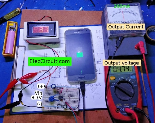
It works quite well. We can measure the charging current of about 250-300mA. But the output voltage drops slightly to about 4.74V. But when it touches the chip, it heats up.
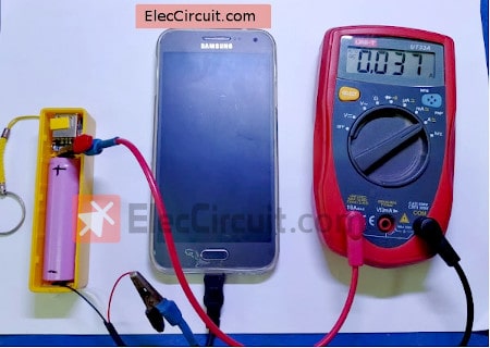
Fortuitously, we have a 3.7V battery. So I want to try to charge my mobile phone. But it doesn’t work at all. Because the voltage is lower than 5V. However, it still has a current flowing of about 37mA.
We experimented with this circuit, it turns out that the output voltage is about 4.8V at about 260mA (0.26A) current. This is enough to charge a mobile phone.
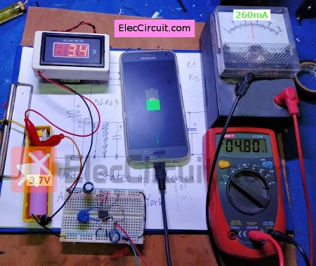
Then, We measure the current of all the circuits. It shows about 0.7A.
However, its efficiency is low, the chip has a higher temperature. We should improve it more so that it can supply more current. which we will continue to learn
Thanks
Onsemi.com produces good products for us to use.
Friends who inspire me and my daughter Let’s try a fun circuit together.
Download This Post
All full-size images and PDFs of this post are in this Ebook below. Please support me. 🙂
GET UPDATE VIA EMAIL
I always try to make Electronics Learning Easy.
Related Posts

I love electronics. I have been learning about them through creating simple electronic circuits or small projects. And now I am also having my children do the same. Nevertheless, I hope you found the experiences we shared on this site useful and fulfilling.
How to convert 5v to 12v
Hello Darren
Thanks for your visit to my site.
You can do it in two ways.
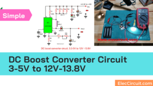
https://www.eleccircuit.com/dc-boost-converter-circuit-3-3-5v-to-12v-13-8v/
https://www.eleccircuit.com/boost-converter-5v-to-12v/
Thanks