Imagine In a few minutes, you know that the electricity will go out. You do not have candles. You only have a flashlight from your mobile phone. But you need to save your mobile’s battery. For emergency use. How will you do?
In your store, there are a 5 watts 220V LED Light bulb and a 12V battery.ฺ But, It is impossible to make the LED bulb bright with only a 12V battery.
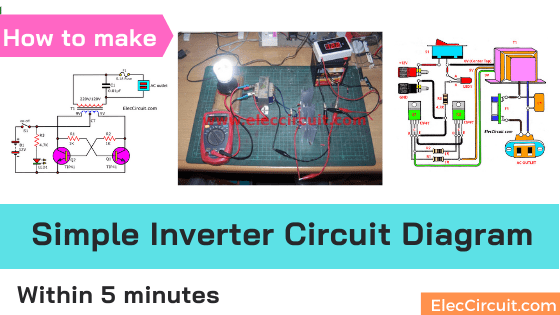
They need some help to make the battery voltage higher enough for that bulb. This is called an inverter circuit there. They can convert a DC 12V battery to AC 220V/AC 120V to apply a small light bulb or a maximum 10 watts lamp.
Here is how to make an inverter circuit within 5 minutes. In 2 simple inverter schematic diagrams below. Just using 2 transistors, 2 resistors, and one transformer only. Is it easy?
They include 2 circuit ideas
- Micro-Inverter circuit diagram using TIP41 or 2N6121
- Super Simple Inverter circuit using MJ2955 (PNP transistors)
Micro-Inverter circuit diagram using TIP41 or 2N6121
If you have 2 NPN power transistors, TIP41 and mint-size transistor, 0.5A. This circuit may be a great choice.
It can convert a 12V battery to ACV in the range of 180V to 220V. At the output frequencies from 30Hz up to 65 Hz.
You can use it for general appliances under 10 watts. For example, Small fluorescent light bulbs, LED lamps, timers, etc.
The LED Light bulb saves more energy than the fluorescent light bulb at same the lightness.
You may like this circuit. Because assembling the circuit you just wiring the parts together by a leg to leg only.
It may take about 5 minutes only to finish this circuit.
Note: Please read “Testing/application” below for real application.
Description circuit
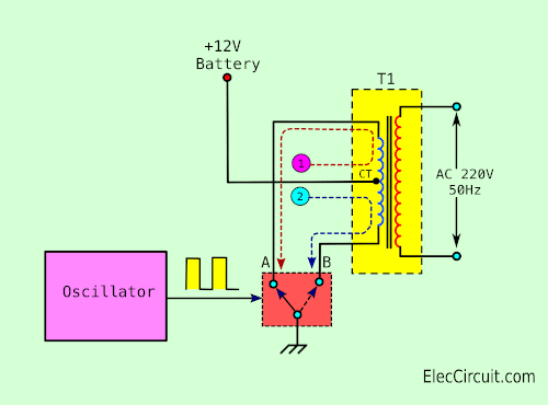
The general inverter circuit uses an oscillator to drive a transformer with a power transistor.
Using dual transistors is push-pull switching to alternately works ON and OFF. Both transistors should have a similar gain rate. But do not need the same.
How it works
Look at the block diagram below.
When entering the power(DC12V) to the circuit. One of the transistors will saturate (closed circuit) faster than another one.
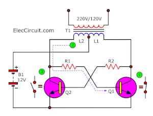
Suppose Q1 has closed the circuit first. So, the collector current of Q1 produces a magnetic field in the coil L2. Then, it gets more base voltage through R1. So, the Q1 quickly into a state of a closed circuit. Also, it makes Q2 is quickly an open circuit.
The condition is like this until the transformer core reaches a saturation point. Thus, the current flows to R1 reduce until cannot make Q1 in closed circuit status. The Q1 is the opened circuit.
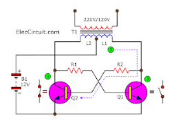
In opposite, while Q1 is slowly changing from the closed-circuit into the opened-circuit status. The Q2 will begin to conduct more currents. The current will flow through R2 to increase a bias current to Q2. It makes Q2 be closed-circuit quick.
Now, the current of the battery will flow to coil L1 in a reverse direction. It causes the voltage induction to be the opposite polarity in the secondary coil of a transformer.
The Q2 will still conduct current until the transformer core reaches saturation.
After that, this process of the closed-opened circuit between Q1 and Q2 will be the same again. As long as, DC12V is fed into the circuit
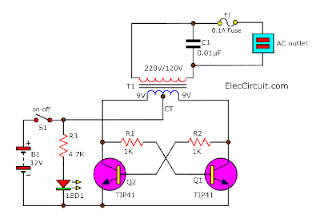
The micro inverter schematic diagram
Look at the complete circuit above. The designer put a few components:
- C1-capacitor across the primary transformer to make the output AC voltage to be smoothed or low noise.
- F1-fuse to protect output and the circuit when overload.
- LED1 shows the circuit is running. Use R3- series resistor to limit current to a safe value.
How to make the inverter
For in the project, use a few components. So, we may use the wiring circuit below, without a PCB layout. I suggest some making techniques, as follows.
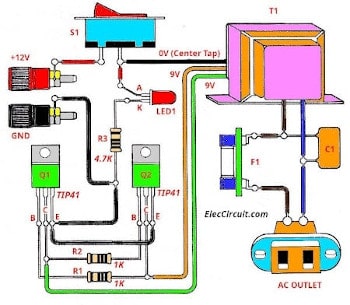
The wiring of this project
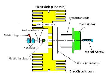
Proper way of mounting the transistor
Look at Fig below.
It is the proper way of mounting the transistor in a heatsink. Use a mica insulator insert between the case and body of the transistor. Then, use a plastic insulator. Next, hold the transistor body with a hex nut and metal screw.
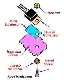
The mounting of the transistor on the heatsink
Remember! Do not any lead of transistor touch to a case or short circuit between these leads.
Check the short circuit!
We may check resistance to be sure that no electrical shorting to the metallic case exists.
Set to dial of the Digital Multimeter(DMM) to CONTINUITY. Then, touch the end of both probes between each lead (B, C, and E) of the transistor and the metal case. It should be silent and read OL.
.
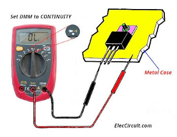
Check short circuit with a multimeter
Testing/application
I test working as follows step:
1. Get the 12V battery, 2.5Ah, or 12VDC regulated power supply, the current is more than 2A for testing.
2. Set the dial of the DMM(Digital multimeter) to ACV to measure the output (outlet).
3. Apply the 12 V battery to this project.
4. Measure the output voltage. You should read voltage between 220V to 330V.
After that, try to use this inverter circuit project to load, 3 watts LED lamp. Because of low power consumption.
This circuit has an output power of about 5 watts to 10 watts only.
As in the above video, LED lamp glows brightly for 3 hours. Because it uses 0.5A only.
Other choices
Since I have limit components.
I assemble parts include 2 x TIP41 with the heatsink, 1K-resistors on the universal PCB board.
I use 0.75A, 9V CT 9V transformer.
But this circuit may provide different frequency and output signal according to device specifications. But it doesn’t matter. Because we use the load as LED light bulbs.
Components list
Semiconductors
Q1, Q2: TIP41 or 2N6121, NPN transistors 40W 45V 4A
LED1: Red LED or as you need.
Resistors (0.5W +/- 5% Carbon)
R1, R2: 1K
R3: 4.7K
Capacitors
C1: 0.1uF 630V AC mylar capacitor
Miscellaneous
T1: Transformer 220VAC or 120V primary coil/10-0-10V, 750 mA- secondary coil
F1: Fuse- 0.1 A
SW1: Toggle switch
AC- plug, mica insulator, LED, plastics, 12 VDC Battery, solid Wires no 20 AWG, nut, and screw, etc.
Super Simple Inverter circuit diagram using MJ2955
From the previous circuit, if it gives low watts output for you, me too. We can change some parts.
For now, I focus on circuits that use the necessary equipment. And only used temporarily.
In the event of adding power is more than 10 watts. It requires the transformer that provides the current over 2A and changes R1 and R2 are 100 ohms 5W instead.
This circuit looks like above tiny inverter circuit above.
But I change both transistors is 2N3055, and the use of R1 and R2 is 68 ohms 5watts.
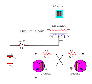
The 15w to 20watts inverter circuit diagram using 2N3055
Other ideas. I check in my store. There are a lot of MJ2955. It is match pair of 2N3055. But it is PNP power transistor.
I hardly ever used them.
Thus, I set new an inverter circuit diagram. See Fig. It is so easy. It two MJ2955, two 68 ohms resistors, and one transformer only.
You see really it is possible!
In this case, I do not need a high power and a long time using. Because I use the power of 10 watts for just a brief moment (30 minutes approximately).
Then, I look for all the parts in my store. I have a lot of MJ2955 power transistors.
Thus, I choose an inverter circuit diagram like Figure 1. It is so easy. It two MJ2955, two 68 ohms resistors, and one transformer only.
You see really it is possible!
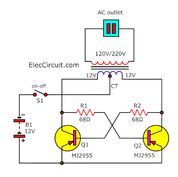
The MJ2955 inverter circuit diagram
In this case, I do not need high power and a long time using. Because I use the power of 10 watts for just a brief moment (30 minutes approximately).
Both transistors and two resistors are set in an astable multivibrator mode.
My friend that is a guru about power electrical tells me. Though circuit style will not have capacitors. But it can generate the frequency. The secondary transformer works as a load that can transform electrical to high voltage. But not sure is 50Hz. It gives a frequency of about 30 Hz to 90 Hz.
Depending on the device, for example, each transistor has different electrical properties. The battery voltage level also has an effect on frequency.
However, if the load is just LED light bulbs. It works without problems.
Let’s build this circuit
This circuit is super simple and tiny in size. I assemble them on the heatsink and connect all wires as Figure in the video below.
Note:
Here is a proper way of mounting the transistor in a heatsink. Remember, check short circuits as above.
Testing
As in the video I use a 12V battery 2.5Ah size as a source. Secondly, I measure output AC voltage as 225 volts. Next, I apply LED lamps to the output. The voltage is lower to 190-volts and can keep up power( light smooths).
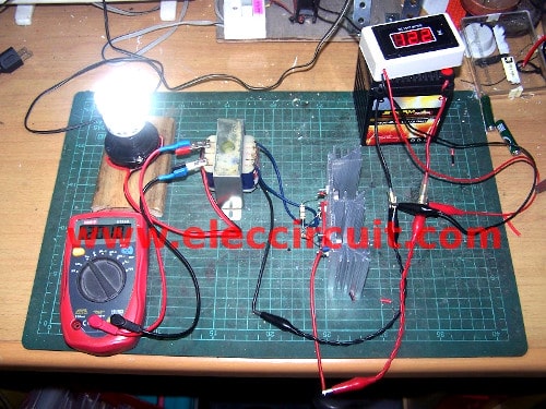
Application this project
The parts you will need
Q1,Q2: MJ2955 or TIP2955 PNP power transistors = 2 Pcs.
R1,R2: 68 ohms 2watts to 5 watts resistors = 2 pcs.
T1: 12V CT 12V / 220V or 110V transformer = 1 pcs.
If you want 20 watts output, use a 1A transformer.
Heatsink, 12V battery, etc.
This circuit has the disadvantage that the frequency is unstable. Therefore it is not suitable for prolonged use and should not be used with high precision loads. But is it worth it? It’s easy and very cheap.
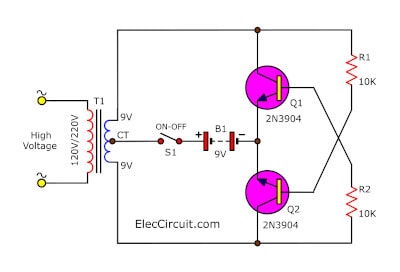
Tiny transistor inverter circuit diagram
In addition, if you want to create one for fun experiments, you can use a small transistor like the 2N3904; it can also output high voltage. But the size of the electrical transformer must also be changed to be smaller. According to the circuit diagram below,
Also, You may use the project below it looks great.
See those circuits you may like it, too
GET UPDATE VIA EMAIL
I always try to make Electronics Learning Easy.
Related Posts

I love electronics. I have been learning about them through creating simple electronic circuits or small projects. And now I am also having my children do the same. Nevertheless, I hope you found the experiences we shared on this site useful and fulfilling.

How much AMP transformer required for this inverter?
#Micro Inverter using TIP41 or 2N6121
can i use tip41 for the transistor?
Yes, You can.
i think we use 20v tapped transformer
can i use mje3055t in place of Q 2n6121
Yes, you can.
i have made this circuit. i hav used 12-0-12V transformer with a rating of 2A.when i give a supply of 12V input, the LED glows but the transistor Q2 gets heated up. but still i am unable to get the output. can anybody help me??
i didnt get the transistor 2N6121. so instead of it, i am using its equivalent transistor D1274.
Bonjour j’aimérais si possible de savoir quel son les transisteurs qu’il faut metre pour haugementer la puissance de cette inverter
AWESOME!!!!
Thanks MR OHM 1970.
what is it power and how much load it can bear.
please help me
The output power is under 10watts.
Hi,Aziz
It can use for 10-30watts load power.
i did’nt get the output plz help me
I love your site. Its interesting
can i use npn 2n3055 or tip3055 instead of pnp mj2955 please help me.
I think in this diagram drew somthing wrong. is this circuit draw correctly. please sir reply me soon bcoz i wanna build this circuit as soon as possible.
Hi, Owahid.
Thank for feedback.
You can use TIP3055 or 2N3055 NPN transistors.
same this circuit : https://www.eleccircuit.com/micro-inverter-by-2n5121/
You can substitute polarity from ground (+) to (-)
and above (-) to ground.
I made the type41 circuit. It did not output 220v. The transistor has become very hot. 0.5 ampere power would.
Hello Günhan,
Thanks for your visit. I am happy that you feel interested in this circuit.
I made this circuit: Micro Inverter circuit diagram using TIP41 or 2N6121
If use 12V transformer the output voltage is drop. So we may use a 9V CT transformer.
At 0.5A or 1A.
Yes, the transistor is too hot. It needs a big heatsink.
Yes, the current use is lower. But I not sure it is 0.5A.
Please watch the video. If you have any questions please tell me.
I want to help you.
I have already made your suggested circuit ‘micro-inverter-by-2n5121’ using D880, and it works successfully. And now my question is if I use TIP3055 or 2N3055 transistor than which resistor I use 1k or 68 ohom. Another request, can you give me the formula to choose right resistor for base bias. I mean which formula you use to choose 68 ohom for this circuit. Please sir help me.
Here you use 12v-0-12v center tap transformer but how many amp would need to produce 50w output. Because in the diagram I saw only 1A rating. And so many thanks for reply my first question. This site is such a blessing for hobbiest like me.
hi.,
how can i add more transistors to make this support for higher loads., in what way., the add-on transistors should be connected.,
can any body please.help
Hi,sumalatha.
It not sure you should use correct size transformer and R1,R2 some time must be use lower than 1K at 5Watt.
#Micro Inverter using TIP41 or 2N6121
Hi,harish.
You can use more transister size than it. or PNP type.
https://www.eleccircuit.com/very-simple-50-watt-inverter-using-mj2955/
But it not sure works well.
If you need simple circuit please see:https://www.eleccircuit.com/220-volts-power-inverter-using-ne555-and-mosfet/
It can use for 50 watt to 100 watts as transformers size.
#Micro Inverter using TIP41 or 2N6121
very helpful and informative
#Micro Inverter using TIP41 or 2N6121
Hi, Joel
Thanks for your feedback.
#Micro Inverter using TIP41 or 2N6121
please how to modify the circuit to obtain the output power equal to 150 wattes i wont to realize it with 220V and 50Hz and 150W in output and thanx a lot
o built this curcuit but the resistane start heated& then one of the tansistor get damage i will try this again…please help..
watt of number resistor
Hi can this inverter circuit be used with a portable battery operated radio with rectifire of course
#Micro Inverter using TIP41 or 2N6121
Hi,hoang anh ky
Thanks for your feedback.
You can use about 2W to 5W or 10W.
Can i use ordinary transformers? Primary winding is 220v and secondary 12 – 0 – 12
HELLO admin,
I have made this circuit with mje3055 and 68ohm/5w resistor. i connect emmiter to ground and transformer’s center to (+) because they are npn transistor but there is no output. both of the transistor got overheated though i use two big heat sinks seperately. but no output,where is the problem please help me sir please.
yup i is a ordnary transformer 12-0-12 0 means centertap (CT)
Hello Sir,
i m making 50watt mj2955 inverter. In this inverter automatic charging system is available??
please corect diagram.
sir what is the use of mj2955 in the circuit ?
dose it work in 5amp trasformer
Hi good work. I will try
How many amp transfor would I use in other to hv 50watt output
Hi aza,
This circuit works.
i wanna know how to make a simple inverter
Hi
can you send your circuits to me
on my mail
thanks
Can i use 5amp transformer
Hi,
did anyone get this circuit to work?
The LED comes on, the TIP 41`s over heat and there is no output
#Micro Inverter using TIP41 or 2N6121
Hi Des,
Thanks your feedback.
This circuit works please check connection of TIP41’s legs.
#Micro Inverter using TIP41 or 2N6121
Hey sir , I saw this diagram its very simple ckt for built a inverter .
But Can u tell me this ckt diagram is accurate? Coz, its look like a very easy ckt. And somwone also reqyested to u to corrcect this diagram .
I want a built a inverter.
I am very thankful if u give reply of my request.
2. 12V to 220V Inverter 180W by 2N3055
if i use 12 v and 7.5 A battery THEN IS THERE ANY PROBLEM
Hi
I need a circuit to convert 5V 2A DC to 12V 0.5A AC supply for powering my dlink router from
usb powerbanks . Please help me to figure it out.
Please, i will need a live working complete circuit diagram foe a 1KVA Power Inverter using MOSFET technology and a 12V battery. I will be very grateful for your timely assistance.
Sir thank you for this circuit it work real good, am a student of electronics engineering who look forward to communicate with you personally on some circuit thank you.
#Micro Inverter using TIP41 or 2N6121
hi I need to know what would happen if my battery tuns low up to around 7volts eould the simple 2N3055 inverter still work????
I am interested in your circuits
can i use it for long time? approx. 5 hours
Sir plz help me,ac voltage get at point below center tap transformer and its value is 15v Ac but transformer couldn’t get step up into 220v,transformer get heat but didn’t give any output.. What is problem in it?… Also how much Ah of battery can I use?
#Micro Inverter using TIP41 or 2N6121
Hai sir, I am a engineering student. I have seen your simple inverter model using mj2955. It was fabulous. So I want to know detail study about it and how it is working. Can you help me
please Sir can I use 0.1uf carpastor 50v
#Micro Inverter using TIP41 or 2N6121
No, you cannot use it. Because of the low voltage rate. You need more 400V.
But sometimes you may not use that capacitor. Try it first. Have a good day!
Please i want to know if you can only use the transistors that you gave because i have T430 Transistor. Thanks
Hi, Miracle
You can try to use T430 transistor. See in datasheet: NPN transistor 10A IC, VCE:400V max. hFE: 800
Source: https://alltransistors.com/transistor.php?transistor=52865
If it receives any results Don’t forget to share.
I like what you are doing. Am learning so much easyer
Hi Alvingreen,
Thanks for your feedback.
I will keep it.
Good day
I love this circuit because it’s simple, and it really works. But please, for the first circuit (without the capacitor), is the output a square wave or a pure sine wave? Please I would be grateful if you reply soonest.
Thanks a lot.
Hello Divine Prosper,
Thanks a lot for your visit.
Have a great day.
This circuit is a square wave. It cannot be used for AC motor.
Please see this: eleccircuit.com/220-volts-power-inverter-using-ne555-and-mosfet/ or
https://www.eleccircuit.com/inverter-12v-to-220v-100w-transistor/
They are easy too. If you create the circuit please do not forget share me.
Thanks again.
Apichet
Thanks.
Please may I know the output frequency or an estimate of frequency of this inverter. It is my pleasure to hear from you soon.
Hello, Divine Prosper
Thank you very much for your visit. I appreciate your question. I am very glad that you are interested in this circuit. I’ve been trying to build this circuit for a long time ago. But unfortunately, I didn’t measure their frequency. However, I think its frequency is around 100 Hz to 400Hz. I believe you can build this circuit and if you measure its frequency. Please don’t forget to tell me.
I’m glad we were friends, Sincerely
Thanks
Apichet