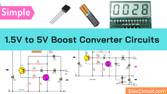
Here is a 1.5V to 5V boost converter circuit. Why it is interesting. Now, small electrical appliances have a microcomputer that requires a 5V power supply and a low current of less than 10mA.
The 1.5V AA battery is cheap and popular. How we can use it as a power supply for that tiny microcomputer.
Recommended: Learn Basic Electronics
Sure, we have many ways to step-up voltage. Using ICs may be a good idea. But If we are beginners or who love experimenting with basic circuits.
In this circuit, we use only small transistors.
Note:
This circuit is one of 5 DC converters using small transistors. All circuits are so easy to learn and having fun.
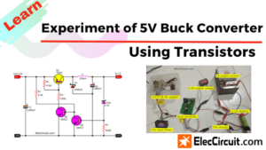
- DC to DC Buck converter working principle
- Switch mode LED driver circuit (Save energy)
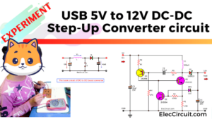
- USB 5V to 12V DC-DC Step-Up Converter circuit
- Simple 12V transistor switching power supply
- 1.5V to 5V boost converter circuit for microcomputer
- 5V to +/- 12V boost converter circuit or higher using transistor
You should read all for more understanding.
How it works
Also, we can use the nickel-cadmium/nickel-metal hydride battery of 1.2V, alkaline battery to these appliances.
The microcomputer requires a low current power supply. This 1.5V to 5V boost converter circuit is small.
So, it can be in the game players, MP3 portable, DVD players.
This 1.5V to 5V boost converter circuit as above is applied from this boost converter into a new circuit.
If you got it, Read next
Single output version
See in the circuit below. It is the single output (5V 10mA) version.
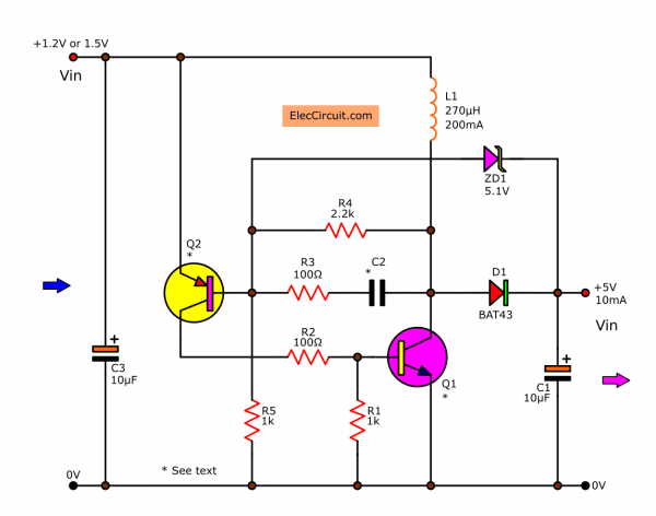
The important is Q1, L1, and D1 like the previous circuit. But additional the Zener diode ZD1 is regulation to makes the stable output.
This circuit converts the 1.2V or 1.5V input voltage up to the 5V. While it can apply the current of 10 mA. This current level is sufficient for the general microcomputer.
Read first for beginners: How do transistor circuits work
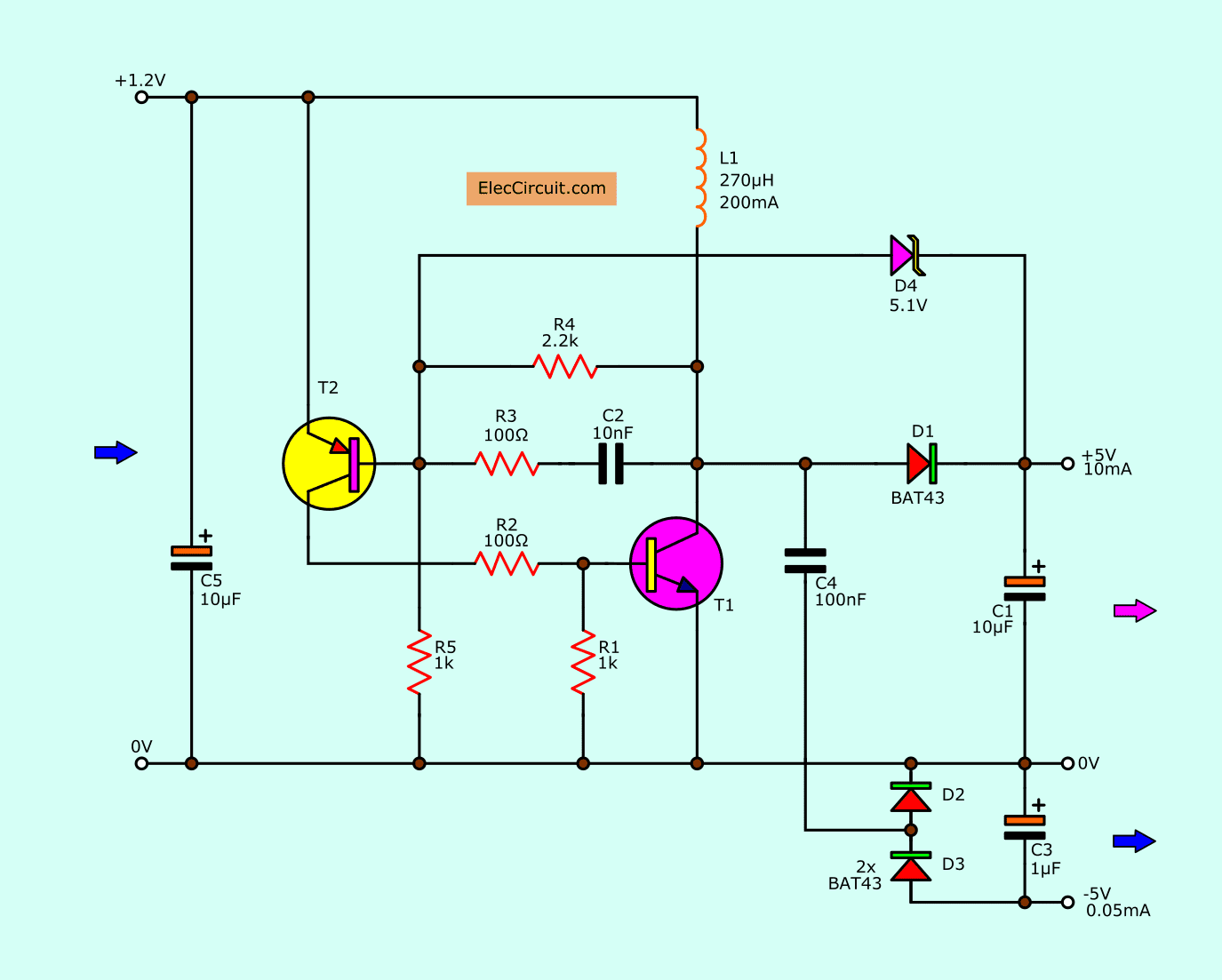
Small LCD display Supply(Dual Voltage)
However, some appliances may have an LCD display inside. For example, game players, MP3 players, etc.
They require the -5V power supply.
We can do it easily. It becomes 5V Dual power supply, +5V at 10mA, and -5V at 0.5mA (approximately).
Look at the circuit below.
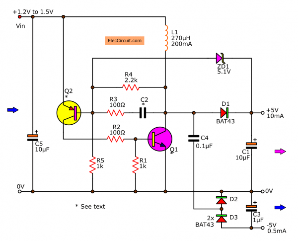
We add C4, D2, and D3. They are the simple charge pump converter, to make a negative voltage, -5V. The current of this section is about 0.5 mA.
How the circuit works
First of all, apply the current(1.5V battery) to the circuit. The current cannot flow through L1. Because Q1 does not get the bias current.
Then, Q2 starts working with the current from 1.5V. And, the current flows from the emitter to the base of Q2 through R5 to be the full circuit.
The Q2 provides the current out of the collector to be a biased current to Q1. The Q1 is conducting.
You may like to see these too.
- DC to AC Converter circuit
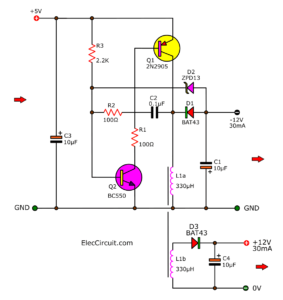
- DC Boost Converter circuit 3-5V to 12V-13.8V
- 12V to 24V step-up converter using TDA2004
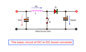
Now, the L1 connects to the ground like a normal boost converter. But the working of Q1 makes the voltage across collector-emitter is lower. They work looks like a switch.
So, It will add quality conducting of Q2, with R3 and C2. Make this system is high performance. Also, Q1 is good working.
And, the L1 passes the high current until the maximum in linear form. After that, the polarity of the voltage across L1 changes.
The performance of this circuit is about 60%. The advantage of this circuit. The voltage drop across it is low.
While the transistor switch on the voltage across between collector-emitter is only 0.2V. But it can supply the high current.
Parts you will need
0.25W Resistors, tolerance: 5%
R1, R4: 470K
R2, R3: 100Ω
R4: 2.2K
Ceramic Capacitors
C2: 10nF (0.01µF) 50V
C4: 0.1µF 50V
Electrolytic Capacitors
C1,C5: 10µF 25V
C3: 1µF 25V
Semiconductors and others:
Q1: BC547 or BC550, 45V 0.1A, NPN TO-92 Transistor
Q2: BC557 or BC560, 45V 0.1A, PNP TO-92 Transistor
D1,D2,D3: 30V 200mA, Schottky Diode
ZD1: 5.1V 0.5W Zener Diode
L1: 270uH coil, 200mA See cheap coil
Note:
This circuit we can use many transistor like: BC546/BC547/BC548/BC549/BC550 for NPN type.
BC556/BC557/BC558/BC559/BC560 for PNP type.
This concept optimizes the performance of the power supply circuit.
Keep reading:
- 3V to 5V boost DC converter
- USB 5V to 1.5V Step Down Converter
- High power LED flashlight with 1.5V battery
Credit: LCD display photo
GET UPDATE VIA EMAIL
I always try to make Electronics Learning Easy.
Related Posts

I love electronics. I have been learning about them through creating simple electronic circuits or small projects. And now I am also having my children do the same. Nevertheless, I hope you found the experiences we shared on this site useful and fulfilling.
pls admin can I use dis cct as a charger for my nokia phone?
Hallo,
I dont quite understand this circuit.
What is the job of L1?
What is meant with:
“When start apply the current do not flow through L1, because not have bias for T1
But the current start at T2 by current from voltage source of 1.2 volts. Flow into emitter pin out to base pin of T2 through R5 go to full circuit.”
I managed to translate it a little bit, but i dont quite get how the current goes from emitter to base?
Tried translation:
“At the start the current does not flow through L1 because T1 does not have its base.
But the current that is applied to T2 by the source Voltage (1.2V)
flows into the emitter from T2 to its base (?)through R5 (1k Ohm) to 0V to complete the circuit.
T2 has a base current (?) >THE current by ARROWHEADS<(whats meant by this???)
So T1 is getting a current onto its collector???
—"
Im willing to translate this for you… but i need more infos, insights as to how this circuit works.
Also would you like to change your circuit images to not have such a solid text over it. And instead use a little bit more transperancy? so that its not as much blocking the circuit?
Hi there,
If I need only the +5V, should I remove C3, C4, D2 and D3?
Thanks.
Nelio.
Can i replace bc560 with bc547
& bc 550 with bc548?
tested and working, authors english is didaster.
to EDWIN: you can replace the transistors with similar ones.. bc560 cannot be replaced with bc 547, cause its PNP!!! i used bc557c (the “c” is not important, versions differ in h21e) for T2 PNP and bc548b as T1 NPN.. the circuit works, it stops to oscillate as you rise the input voltage, it has to be low as described. the critical part is the inductor, i used 330uH / 0,5A, Rdc (max) = 1 Ohm (https://www.gme.cz/tlumivka-radialni-09p-331k-fastron), it didnt work with 2.2mH with around 30 Ohms Rdc.. also didnt work for higher voltage (switched zener for 10 volt one), it was still around 6V out..
to NELIO: yes, i did remove those too..
can u plzzz elaborate ????? @KiLLA CZECH REPUBLIC
Can u Plzz elaborate KILLA CZECH REPUBLIC
Hello, Dikshit Thakuria
I am sorry for my English. I hope my English is improved. I will try to rewrite it.
Wuz Up???????????????
Not Nice Comment Dikshit
@ Kocy
T2 is a PNP transistor and you need to make the base voltage lower than the emitter by around 0.65V. This is being done by putting a pull down resistor R5 while the emitter is connected to 1.2V. This is the base current path that the author was trying to explain in order to turn it on and provide base current to T1 to turn it on also. With T1 starts to conduct, it provides additional base current path to T2 from 0V through R3 and C2 to make its collector further conduct. T1 continues to conduct until it could no longer support the current rise of L1 due to its hfe so it will suddenly turn off…. this process is repeated over and over which is called an oscillation and thus the circuit is an oscillator.
Thanks a lot for helping.
You explained very well.
Yes you are right
BC 548 and BC 558 30 volt transistor. İnstead of must be BC547 and BC 557 (45 volt)
Hi again,
I am happy that come back to my site.
Your advice is great. I just update it.
Hope you are healthy.
See you.
Hi, do you have pcs circuit for my appliance to use,
My refrigerator, my tv, my electric tools
From a 12v battery input to 12v,24,48,60,72,90,110,220volts
I appreciated your help
Thank you