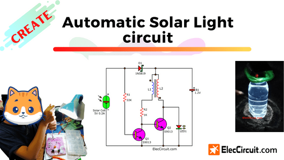
Let’s create a simple automatic solar light circuit. My kids made it for daily use and to learn electronic circuits. They work well, so we are happy.
During the night, little white light coming from a LED can help you live more conveniently in the dark. It does this even without power from the outlet. Because it uses a battery, which is charged from a solar cell during the daytime.
To achieve this, we experimented with multiple 4 circuits, which were made according to the conditions and parts we had at that time.
We list them in order of the latest updates.
Note: Each circuit has different Pros and Cons. They all are excellent if you learn them all. Sometimes the old circuit might help you achieve your goals.
Automatic Solar Light circuit
We built this circuit to replace the old circuit, which her brother (my son) had built many years ago. Now my daughter intends to try to develop from the original circuit to be easier and more economical (more clever).
My daughter installed this circuit in the chicken pen at the end of our garden (No house AC power). Our chickens only need a little light, just one LED is enough. If there is too much light, the chicken cannot sleep.
How does it work
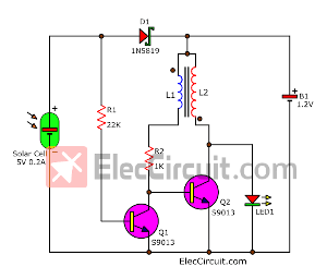
Look at the circuit below. At first glance, we only use a single 1.2V Ni-HM rechargeable battery and white LED which require a voltage of about 3.3V. So, there is no way the white LED will light up.
But with a simple unregulated flyback circuit or Joule thief circuit, it is doable. Especially the toroidal inductor (L1 and L2) which has a quite interesting working process and is somewhat new to us.
I came across the idea of this circuit by chance. While we are looking for examples of women who excel in electronics. We found Jeri Ellsworth’s YouTube channel. She’s a very talented woman. One interesting piece of content is Minimal Solar Night Light Circuit Read more
Although this circuit may look simple, it is very challenging to explain to my daughter. I used lots of illustrations to help explain.
Battery Charging during daytime
It will change to charging mode automatically during the daytime. Let’s look at a rough illustration showing an interesting sequence of the current’s flow.
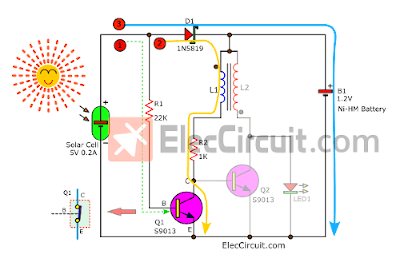
Step 1: The electricity from the solar cell flows through R1 to the base of the Q1 transistor causing it to conduct current from C to E. It is like a closed-circuit switch.
Step 2: From which the working of Q1 allows more currents to flow through L1, R2, and Q1(C-E pins) to the ground. But since the voltage between the C-E pins is very low, less than about 0.1V. It is not enough for Q2 to work. So, the flyback circuit is not working.
Step 3: The largest amount of current from the solar cell flows through the D1 Schottky diode to charge the B1 Ni-HM battery. We choose the Schottky diode because the voltage drop across it is only about 0.1V-0.2V. Makes charging voltage to the battery better than ordinary diodes.
Notice Now the battery voltage (under 1.5V) flows through L2 and stops at the pin of LED1. But LED1 still goes off. Because LED requires forward biased and the level voltage exceeds 3.3V.
LED turns on at Night
On the other hand, when night comes, there is no more electricity from the solar cell, only electricity from the battery. This current cannot flow through D1 because it is reverse biased. So no current flows through R1 and the base of Q1. The Q1 doesn’t work anymore, between its C-E pins is like opened-circuited switches.
The current starts to flow through an unregulated flyback circuit or Joule thief circuit. This part is a voltage booster circuit or step-up DC converter circuit, very small and easy to build, and suitable for low current loads.
The circuit has self-oscillating by rapidly switching the transistor on and off without a capacitor.
The toroidal inductors L1 and L2 are wrapped around the same ferrite core. But they always have opposite directions, causing the direction of the current in the coil to differ as well.
Let’s look at the step-by-step process.
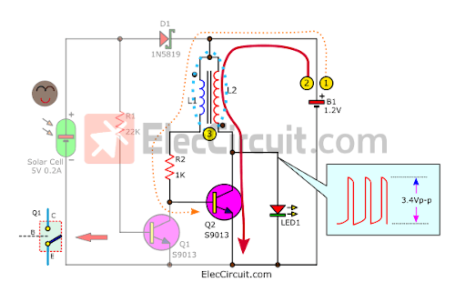
Step 1: The current flows through L1, R2, and the base of Q2.
Step 2: The Q2 is in the saturation states that cause the C-E pins to look like a closed switch. Since VCE will be only about 0.1V. So, there is not enough voltage to output to LED1. Look at the signal as the voltage range this part is always near 0V.
Step 3: At the same time, the Q2 allows a higher current flows through L2, this causes its magnetic field to inflate abruptly and induct the energy to the L1 inductor in the reverse direction. Creating a short pulse of negative voltage into the base of Q2 causes it to immediately stop working.
But because inside L2, there is a lot of stored energy. It will discharge these energies in the same manner as the battery voltage. Alongside the 1.2V battery, creating a similar situation as connecting batteries in series and inevitably there will be an increase in voltage.
Causing the LED1 to immediately have a higher voltage level. (according to the oscillator signal, the highest peak is 3.4Vp-p) This is enough to have the LED1 turned on.
When the energy in L2 is exhausted, the same process will start over again; the current will flow through L1 and R2 causing Q2 to work.
This circuit is very interesting, this explanation is for the hobbyist level. But if you want to learn at a deeper level. You can learn more HERE.
How to build
First of all, the components should be ready first.
Components list
D1: 1N5819, 40V 1A, Schottky Barrier Diode
Q1, Q2, or equivalent, 40V 0.5A, TO-92 NPN Transistor
0.25W metal/carbon film Resistors, tolerance: 5%
R1, 22K
R2: 1K
LED1: White Super bright LED
Solar cell 3V to 6V 200mA
B1: 1.2V AA batteries 1,500mAh
L1, L2: Toroidal inductor each coil 20 turns of 36 AWG wires on 10mm DIA, toroid core.
Recommended: If you are a beginner, read Electronic components list with images.
We found a toroid core in compact Fluorescent Light bulbs that are about 10mm wide. They may be larger in size but they should have a similar effect.
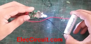
We solder the wires directly to the battery, not using the battery holder is for convenience and economics.
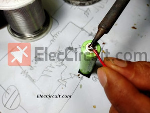
Sometimes, after using it for a long period of time, the battery holder may come loose, causing the circuit to malfunction. But always clean the soldering point first. And don’t solder for too long because the battery starts to deteriorate when the heat exceeds 60 degrees Celsius.
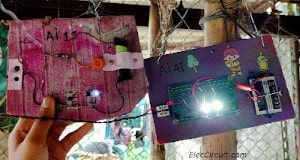
This circuit is very easy to build. My daughter assembled it by soldering the pins directly without the PCB. And place all the devices (except the solar cell) on a wooden board.
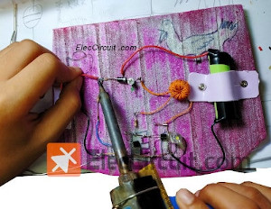
My daughter tested the Automatic Solar Light circuit by obscuring the solar cell to notice the LED turn on. It worked easily.
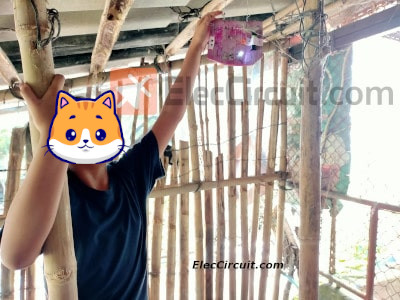
Installing the Automatic Solar Light circuit in the chicken coop works fine. We are happy.
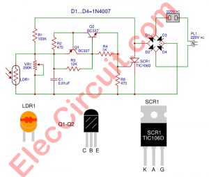
Automatic on-off solar light circuit
This is the first Automatic on-off solar light circuit that the children built. We chose to use a 2 x AA nickel-metal hydride battery with a total voltage of 2.4V at 500mAh. It needs to use a current of about 50mA – 80mA.
As this solar LED garden solar lights circuit. We use the relay to control the current because it’s easy. But Relay works by Coil which uses a higher current of about 80mA at 12V. The solar cell has 3.5V 100mA only, so it cannot use both the relay and to charge the battery.
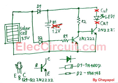
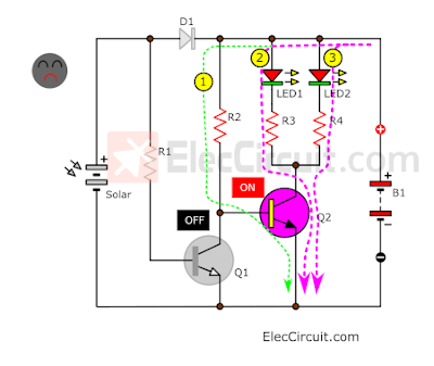
Thus, I chose to use transistors instead of the relay, until it is the circuit below. The small base-emitter current controls the larger collector-emitter current.
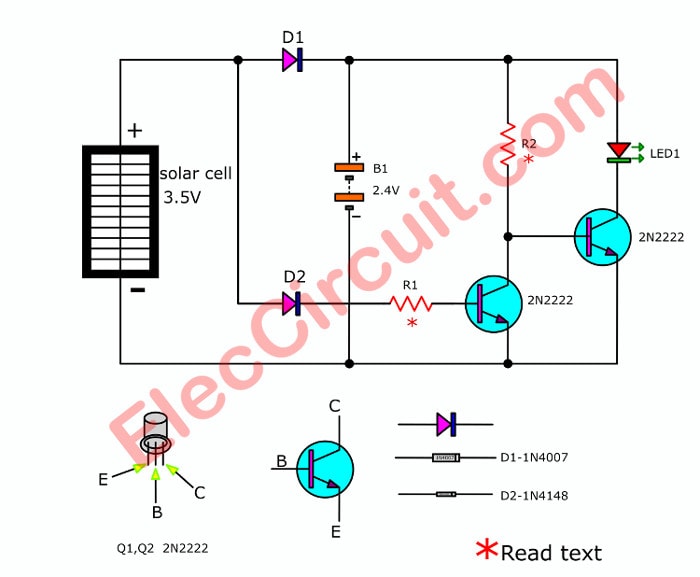
During the day, the solar cell has voltage to D1-diode to bias transistor Q1 it conducting collector and Emitter closed, so it does not have the current bias to the base of Q2. It is OFF so the LED will go out.
At the same time, the solar current will charge the batteries B1.
When no sunshine, no solar current to base Q1, and it does not work. Then, the battery’s current will flow to R2 to base Q2, making it turn ON, and the LED will glow more brightly.
Read also: DIY Flashing Bicycle LED Taillight Circuit
Parts you will need
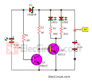
D1: 1N4007, 1000V 1A Diodes
D2: 1N4148, 75V 150mA Diodes
Q1, Q2, 2N2222, 75V 0.6A TO-18 NPN transistor
R1, R2: 1K 0.25W Resistors
LED1: 5mm Orange LED
Solar cell 3.3V-3.6V 100mA
1.2V x 2 AA batteries 500mAh
How to builds
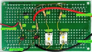
We assembled the circuit on a breadboard and tested it in the sunshine.
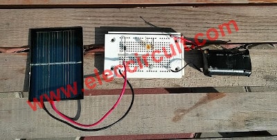
We tested the Simplest automatic solar led light circuit in the video below.
Want more brilliant ideas? Here’s how to get them through electronic circuits.
Water Bottle Automatic Solar Light using 1.2V Battery
Over time, smaller-capacity batteries are becoming more and more difficult to find. We, therefore, modify the circuit. for more convenience
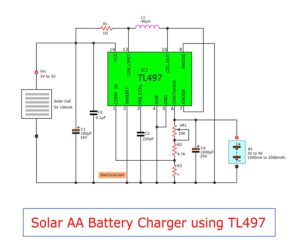
If we don’t have 2 AA batteries. We have only one. We have many ways to use one AA battery to drive LEDs. Now we use a Step-up DC to DC converter circuit below, it can convert 0.9V-4.5V to 5V for a mobile charger. It is much cheaper when buying 10 pcs; it costs 0.8$ per one only. oh! cheaper than AA rechargeable batteries.
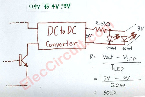
Cut old LED then instead it with the step-up DC to DC converter circuit to drive 2 LEDs, R1 to reduce safe current for LEDs. We can find the resistance of R1
The formula is:
R = [Vin – V (LED)] / I (LED)
Vin = 5V(USB) ; VLED = 3V ; ILED = 40mA = 0.04A
R = (5V – 3V) / 0.04A = 50Ω
We can use 56Ω 0.5W Resistors.
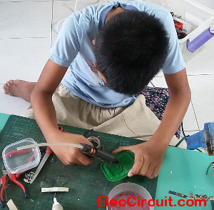
How to assemble Circuits
We assembled this circuit into a universal PCB Board as shown below. We tried to use the objects close to us to save money and preserve the environment. So, we use a kitchen box to use this circuit.
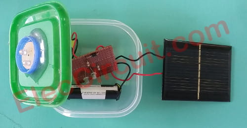
Assemble this circuit into the small kitchen box.
We use plastic water bottles as LED lamps. Because he noticed that when we put some water in the bottle, it became a convex lens. Increase the brightness of the light.
IMPORTANT We need to glue the box and bottle cap well
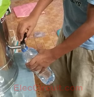
How to make LED lamps from water bottles
First, fill clean drinking water into a bottle of water almost full.

Then, add a little bleach down. It will make the water clean and Non green lemongrass, although it was sunburned.
Testing
When we complete the circuit, bring it to the garden or in the sun. Next times test this circuit at night.
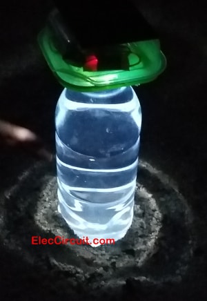
We will see the light of the LED in moderation. The Water Bottle Lighting Ideas Increase the brightness of the LED as well. LED lighting is long enough throughout the night.
Simple Solar light circuit version II using Li-ion battery
Previously, we had built the Automatic Solar Light circuit and had been using it for many months. It has fair efficiency for everyday lighting. But this circuit has two problems: a dim light level and batteries that are hard to find and quite expensive.
But now my daughter has built this Simple solar light circuit version II. It has a better performance than the first one.
- It got far brighter because she used two white SMD LEDs.
- Use a 3.7V Li-ion battery instead, which is widely used. Making it easier to find than the 1.2V Ni-MH battery.
- The circuit is also simpler.
And of course, we also use recycled components. Thus saving us money and helping us learn more about using them.
How it works
Now let’s look at the block diagram of this circuit. It will help us visualize the circuit we would need.
First, let’s say it’s daytime.
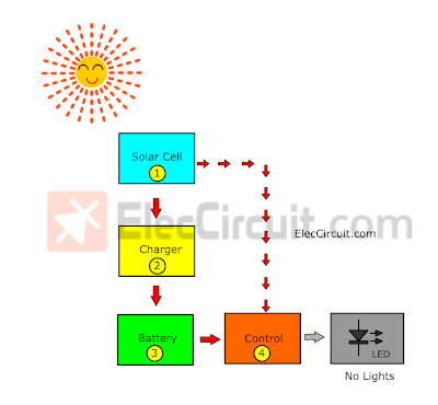
An electrical current from the solar cell charges the battery, and some current also goes to the control, turning the LEDs off.
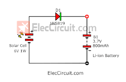
Simple Solar Li-ion battery charger circuit
This is the simplest Solar Li-ion battery circuit, consisting of only three components:
- Free 3.7V Li-ion Battery
Nowadays, we prefer to use Li-ion batteries over other types of batteries because they have higher efficiency. It supplies a voltage of around 3.7V (up to 4.2V). Similar to a lead-acid battery, it doesn’t need to run out of power before recharging; it also maintains power for a long time, among other advantages. Which we will learn about more later.
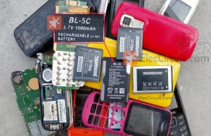
This type of battery can usually be found in old mobile phones and other similar devices. They come in 3.7V 800mAh to 1000mAh. Alternatively, you can get a BL-5C for about $1, which is cheaper than a 1.2V 950mA Ni-MH battery.
It has similar properties to lead-acid batteries in that when the power is full, there will be a voltage of about 4V. While charging, be careful not to let the voltage exceed 4.2V and should charge with a low current.
Recommended: Recycle Free Li-ion battery from E-waste
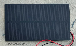
6V 1W Solar cell
Another important component of this circuit is the solar cell panel, which should be capable of supplying a voltage of about 5V to 6V with a size of 1W to 2W. It will supply a current of about 100mA.
When exposed to sunlight for about 5 to 7 hours, it should have charged the battery to 80% or more. It would not exceed the voltage rating of the 4.2V battery, complying with battery specifications.
This low current does not make the battery heat up at all. We have tried this method many times and in many circuits. It has worked well and is suitable for small and economical circuits.
Assume we use an LED (load) that consumes about 60mA of current, but the battery has about 600mA of current; it can provide light for about 10 hours, almost the entire night.
Read Also: Simple Li-ion Battery circuit with automatic cut-off
- 1N5819 Diode
We only use a single diode to prevent reverse current from flowing from the battery to the solar cell.
In the circuit above, the current from the solar cell flows through D1 to charge the Li-ion battery. When there is less sunlight, the higher voltage from the battery cannot flow back to the solar cell.
Because there is a D1 blocking it, the current can flow only one way. The energy in the battery is stored and gradually increases until it is full.
In contrast, at night or without sunlight, there is no power from the solar cell, as shown in the block diagram below.
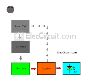
So, there is no power from the charger as well. The control detects this state. It then switches to driving the power from the battery to light up the LED instead.
Free Super bright LED
We are going to use this super bright LED we got from recycling a white SMD LED from the broken T8 tube. It is very bright; for two LEDs, it uses only 60mA of current. We connected them together in parallel and connected the current limiter resistor for each LED.
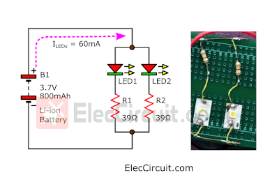
When used with the 800mAh Li-ion battery, it can remain on for more than 10 hours, or almost the entire night.
Turning it into circuit diagram
Next, we have to come up with the circuit according to the block diagram above.
During the day
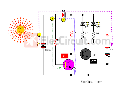
(1) The solar cell receives sunlight, generating electricity to charge the battery through D1.
(2) At the same time, some current will flow through R1 as a biased current to the base of Q1. It causes Q1 to conduct current or turn on.
(3) The main current flows through D1, R2, and the collector-emitter of Q1 to the negative. Thus, there is no biased current to the base of Q2, turning off Q2 and the LEDs as well.
Read also: Small Automatic Plant Watering with a Solar Cell Power System
During the Night
Now there is no power from the solar cell at all. So, there is no current flowing through R1, and Q1 also turns off.
(1) The battery is fully charged, so the current flows back out. But it cannot flow through R1 because it is blocked by D1, which is in a reversed bias state.
Forcing the current to flow through R2 instead, as a biased current to the base of Q2.
(2) and (3) are in play after the Q2 is turned on and drives a main current through both LEDs. So, LED1 and LED2 light up.
Next, we take each part and assemble them together into a complete circuit.
Read more: Simple Circuits
How to build
My daughter built this project on a solderable breadboard PCB and a wooden board because it’s simple and economical.

Conclusion
After we have created this second version of the Simple Solar light circuit, we know that it is more efficient and easy to build than the previous one. Because the SMD LED is very bright and the 3.7V Li-ion battery provides higher power with a smaller size.
In the future, we will try to build a larger circuit, and we hope it will have more use for you.
GET UPDATE VIA EMAIL
I always try to make Electronics Learning Easy.

I love electronics. I have been learning about them through creating simple electronic circuits or small projects. And now I am also having my children do the same. Nevertheless, I hope you found the experiences we shared on this site useful and fulfilling.
it’s wonderful & nice.
what can I change if I want to use a 12v bulb. Thanks I will be grateful.
Great Design///Simple and Cheap To Construct!!!
@Eric A Resistor is needed for The Led. We Must Connect The Resistor Between the Cathode Of LED1 and Collector Of Q2. Assume V led= 2 v and I led =10ma. Now We can Calculate The Value Of This Resistor/// Vin – V led / I led = 12v – 2v / 10ma = 1 k ohm or 1,000 ohms..Circuit Done!!!! We are Just using OHM”S LAW and KIRCHOFFS VOLTAGE LAW here!!!!! GOOD LUCK with Your Project!!!!
Hi, I’ve been using this circuit for two weeks and it worked well. But the only problem is, it seems like the circuit doesnt allow to charge battery to full. I use 5v solar panel to charge 3.7v battery (4.2v at full as read in multimeter). Let say at 12 pm, the battery charged to 4.0 v, but it never reach the maximum full state (4.2v) untill dusk, it stucks in 4.0v even the sun bright all day. How to fix this? Thank you… 🙂
Hi Nick,
Thanks
Hi , sir
I virender from kaithal Haryana . I have interest in slolar light .
I think that you would have been better off with a Schottky Diode for D.1. in the Solar Charger part of your first design.
I like your water idea for spreading the light produced around a bit more.
Hello Michael Robertson,
Thank you that you suggest us. It is very useful.
I read your projects i see i like your some circuit
Hi,
Thank you. You like our project. If you read our article and don’t understand, you can comment and ask.
I and my dad will continue to do so. 🙂