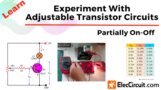
In the previous articles, we learned about using a transistor as a switch, that was, either completely on or off. But circuits such as the audio amplifiers will require the transistor to be partially on, which is very interesting.
But it can be quite a difficult subject for beginners who just started learning electronics to understand, one of which is my daughter. Nevertheless, we hope that this article on this subject may be useful for those who are interested.
Recommended:
Try dimming the light bulb
Normally, this will be the task of the potentiometer, like in the light dimmer circuit. But the transistor can also do this as well, with the difference being that instead of a rotating knob, transistors require voltage to adjust.
Suppose that we want to reduce the brightness of the light bulbs. We may infer that limiting the current flowing through the light bulbs will also lower their brightness. The simplest component that will help you achieve that is the resistor.
The higher the resistance, the lower the current flows to the light bulb, thus lowering its brightness. Whereas, when the resistance is low, the current flows increase, as does the light bulb’s brightness. Easy, right?
The potentiometer is a type of resistor whose resistance value can be easily adjusted with only a rotating knob. May also be known as a variable resistor (VR).
So, we try to connect the potentiometer directly between the power source and the light bulb, as shown in the picture below.
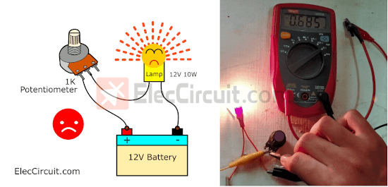
We use a 1K potentiometer and a 12V 10W light bulb here. It was fine at first, but when we lowered the resistance to around 60 ohms, as the light bulb got brighter, there was a burning smell and smoke coming out of the potentiometer.
When we measure the current, it hovers at approximately 0.7A. Which causes the potentiometer to overheat and eventually die.
This indicates that it is not suitable for use at high currents. Instead, we should use transistors when it comes to high-current drivers.
Basic partially on-off transistor circuits
Let’s try making the transistor partially conduct current. Normally, when using a 12V battery to power a 12V 2W light bulb, it uses around 0.13A of current. So the S9013 transistor is the is the best pick in this case, as it can withstand current up to 0.5A.
Now we put together a simple experimental circuit, as shown below.
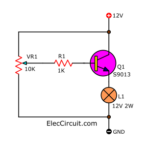
When we rotate the knob on the 10K potentiometer (VR1) counterclockwise to the leftist position, the light turns off. Then, slowly rotate the VR1 knob clockwise, and we will start to see a light from L1 brighten as we go. Eventually, when we reach the rightist position, the L1 will receive full current and light up brightest.
Voltage divider using a potentiometer
So, in this circuit, we can control the brightness of the light bulb by adjusting VR1.
The composition of VR can be thought of as two resistors in a series or voltage divider circuit. When turning VR to the left or down, the resistance of RB will decrease. Reducing the output voltage, causing the current flowing through R1 to decrease as well.
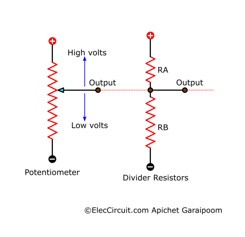
Likewise, if we turn VR1 up or to the right, the output voltage increases as well as the current flowing through R1. The transistor, thus, drives current to the light bulb higher and higher until it reaches its maximum.
We see that as the voltage from VR1 increases, the current also increases, because the RA’s resistance is lower than the RB’s.
Next, we want to know if the voltage levels at B and E of Q1 affect the IC or not. So, we change the position of L1 to a common emitter, as shown below.
We start by adjusting VR1 until the VBE measures 0.5V, and then we measure VCE and IC. And adjusting the VR1 until VBE reads 0.55V, then measuring VCE and IC again. We do these measurements a dozen times with a VBE increment of 0.05V. Then we combined the measurements in the table below.
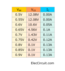
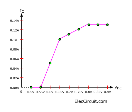
We see that when VBE is lower than 0.6V, there will be no IC at all, and the VCE remains the same as the power supply, which is 12.08V. But when the VBE gets higher than 0.65V, we start to see IC readings, and the VCE decreases because of the transistor conducting current. The IC reaches the highest point at VBE of 0.8V, so even if VBE goes up higher than this, the IC will still remain at 0.13A. We can see this clearly in the progression graph below.
One interesting point is that when the output of the VR1 increases, so will the current flowing through R1, causing the base bias the transistor received to increase. Thus making the transistor amplify the IC current.
Want more brilliant ideas? Here’s how to get them through electronic circuits.
Partially on-off Darlington transistors circuit
Next, if we want to use a bigger load, like a 12V 10W light bulb, we would need another transistor, a TIP41, in the form of a Darlington pair. This transistor formation is good for driving a large load with a little input current.
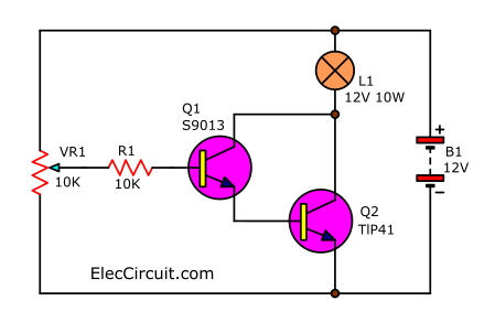
First, we turn VR1 all the way to the left; L1 turns off during this time. Then, as we turn VR1 to the right, the L1 will start to light up, reaching its brightest when VR1 turns right all the way.
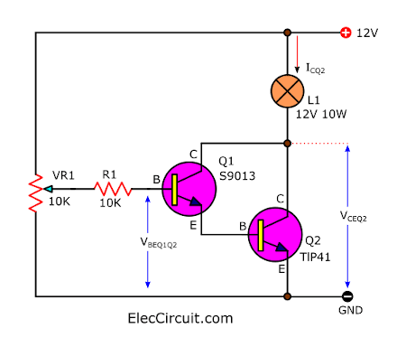
To understand it better, let’s take measurements of the voltage at different points and put them all into a table.
With the same procedure as before, we will see that when VBEQ1Q2 is lower than 1.2V, there will be no ICQ2 flowing through Q1 at all. Also, the VCEQ2 voltage remains the same as the battery, 12V. But when VBEQ1Q2 gets higher than 1.2, the ICQ2 current will increase and the VCEQ2 voltage will decrease. As the VBEQ1Q2 rises to the stable point at around 1.4V, the ICQ2 will now be at its highest at 0.69A, as the load requires. And the VCEQ2 also reaches its lowest at 0.81V.
Conclusion
The transistors are suited for a current amplifier to be capable of driving a light bulb. It can work at a methodical pace with the current at the B of the transistor, which is also known as the IB. As B increases, the current flowing through C and E (IC) will increase as well.
A key requirement is that each transistor must receive a bias voltage between B and E (VBE) of about 0.6V to 0.8V first.
The transistor operating in this manner is often used in amplifier circuits. Which, in the future, we will utilize in our design of a small signal amplifier circuit.
Read next: Designing small signal amplifier circuit using transistor simply
GET UPDATE VIA EMAIL
I always try to make Electronics Learning Easy.
Related Posts


I love electronics. I have been learning about them through creating simple electronic circuits or small projects. And now I am also having my children do the same. Nevertheless, I hope you found the experiences we shared on this site useful and fulfilling.