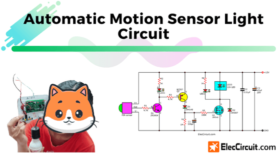
This is a Simple Automatic Motion Sensor Light Circuit. When we use battery electricity for lighting—even with LED light bulbs that consume very little power—for an extended period of time, it also drains much of the battery’s power.
So, is there a way we could save as much electricity as possible?
In some places where LED lights are installed, there is no need to leave the lights on all night. Such as in front of the bathroom, in the corridors, or in some other places. In such places, we could install a switch to turn them on or off when needed.
But would it be better if, say, the light turned on by itself when people walked past, stayed on for about 5 minutes, then turned itself off?
And if that person walks back within those 5 minutes, for example, in the third minute, the system will start another 5-minute timer. So, the total time that the LED remains on is 3+5 = 8 minutes.
Or to make it clearer for you.
I usually leave the 12V 3W LED on for an entire night, or about 10 hours. This LED needs a current of 3W/12V = 0.25A per hour. A total of 2.5A for 10 hours of use, so we need to use at least a 2.5Ah battery.
But if we could just use the light for one hour per night, the current we need would be 10% (0.25A) of the 2.5A that we would normally need, leaving us with 90% remaining energy.
When we use this circuit, we will only need to use the light for under an hour per night. It will help us save a lot of energy.
How it works
This circuit is similar to the Motion detector alarm circuit. We just swap out the main component, a 12V siren, for the 12V LED light bulbs, which have a block diagram as shown below.
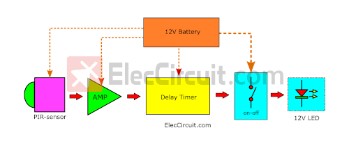
Each block can be divided into:
- 12V battery as the power supply.
- The same PIR motion sensor as before.
- The same amplifier circuit.
- New delay timer, since the PIR motion sensor cannot have a time delay of more than 200s. So, we need to add in an additional circuit to increase the time delay to 5 minutes, or 300s
- A better on-off controller: we choose a MOSFET over a relay because of its better current efficiency.
New delay timer circuit
The principle of a timer circuit that we are already used to is to keep the voltage at the load or output with a capacitor and then gradually release the voltage continuously until it runs out.
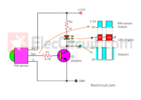
Let’s start with something we already know: the amplifier circuit.
And the block diagrams below show the two ways that we may make a timer; we could utilize them as ideas for our timer circuit design.
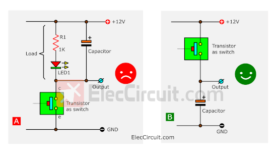
In this case, the transistor will be acting as a switch. The left image (A) shows the capacitor connected to the load in parallel, which makes it impossible for the voltage to get out the way the timer circuit does.
So, what we should do is change the position of the switch and capacitor to what’s shown in the right image (B). When the switch switches on, the current will get charged into the capacitor, and when the switch switches off, the current within the capacitor will get discharged, as is the principle of a timer circuit.
But since this is a common emitter transistor amplifier circuit, the placement of the NPN transistor as a switch would not match the right image (B).
We also do not want to change the amplifier circuit. So, we need to change its layout to what’s shown in the circuit below.
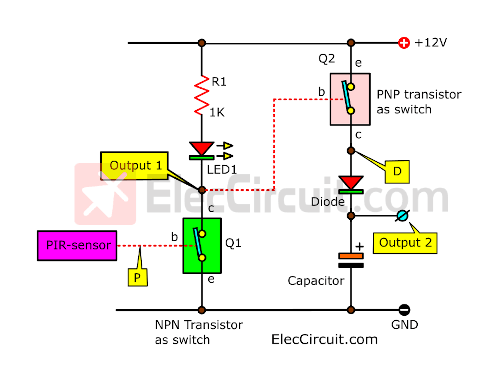
The additional circuit is the common emitter amplifier circuit, which uses a PNP transistor instead.
It will conduct current only when the Q1 turns on or C-E becomes a closed circuit. At the base of the PNP transistor, thus receiving forward bias, causing it to conduct current.
Thus, letting the high current from the 12V battery flow through its E to C and through the diode to charge the capacitor. Also, Output 2 will have an increased voltage level of almost 12V, and it can keep this voltage level for about 5 minutes or so, even after the input signal has already been gone.
We put the diode there to protect the capacitor’s voltage from flowing back into the PNP transistor.
Learning through signal graphs
We want you to understand it thoroughly. So, see the signal graph below comparing P point, Output 1, D point, and Output 2.
Read more: Simple Circuits
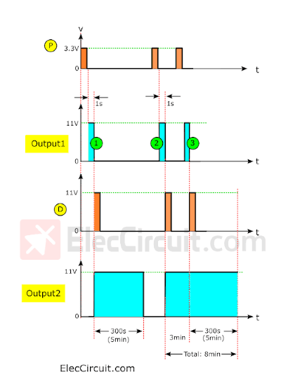
When we walk past the PIR sensor, there will be a 3.3V pulse signal at the P point. Then, around 1 second later, the state of this signal will change from High to Low.
Then, Output 1 will send out its first pulse signal with the same time span as the P point, about 1 second. But with a higher voltage of around 11V. And when this signal starts to drop, there will be a pulse signal at the D point in the same manner.
The current at the D point will flow through the diode to charge the capacitor, causing Output 2 to have the same voltage level of 11V as well.
After 1 second, the D point’s pulse signal state will go from High to Low, but at Output 2, the voltage level will remain at 11V for the next 300 seconds, or 5 minutes or so. then return to Low as usual because of the capacitor discharging.
And then, when we walk back past the PIR sensor again, it will give out the same signal again. And at Output 1, there will be a second pulse signal for 1 second. At the D point, there will be a pulse signal that has enough voltage to charge the capacitor again. The voltage level at Output 2 will remain the same at 11V, as before, even when we have already passed.
But if we were to walk past the PIR sensor again in its third minute, the process should be the same as before. With the third pulse signal at Output 1 and the pulse signal at the D point again, there will be a current to recharge the capacitor and discharge it again, making the total time for Output 2 8 minutes.
With these ideas as a foundation, let’s try to create a simple timer circuit with them.
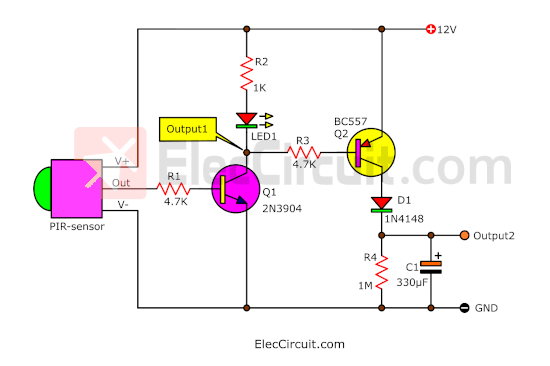
It works well! We added R4 to adjust the time constant to what we desired, which is around 5 minutes. As for R3, it helps decrease the base current for Q2 in the same manner as other transistor circuits.
But at the moment, the current output of Output 2 is still very low, unable to drive a load or the 12V 3W LED. It would need a current of around 0.5A or more.
We have many ways to deal with it; usually, we would choose a relay to turn the load on and off. It is easy, but there would have to be a bit of current running through a relay coil at all times, which is around 30mA or higher.
Thus, we have chosen a MOSFET instead of a relay because of its low noise, no movement mechanism, and better suitability to work as a switch than a transistor. For this exact one, the IRF540, it can endure a current of about 33A and a voltage of around 100V.
In the circuit below, we put all the components together, turning it into a complete Automatic motion sensor light circuit.
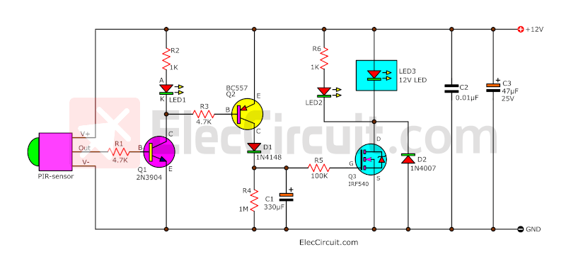
LED2 is to indicate that the load is working.
C2 and C3 help reduce the unwanted signal noise that may cause the circuit to malfunction.
Building this circuit
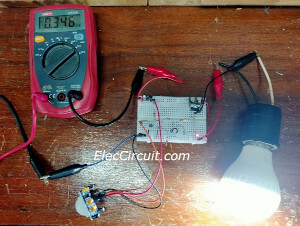
My daughter tested this circuit first on the breadboard to see if it worked fine or not.
After seeing that it worked fine, the next step is to assemble it into a Solderable Breadboard PCB
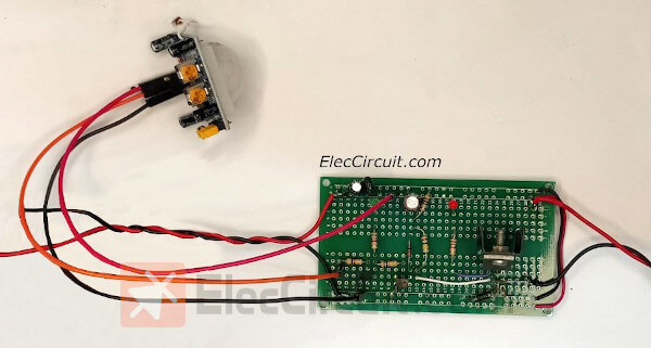
We have been using it for a few months now, and it has been working great so far.
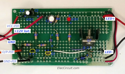
The component layout of Solderable Breadboard PCBs
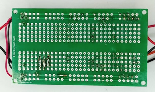
Bottom of Solderable Breadboard PCBs
Note: We should adjust the delay time on the PIR motion sensor to a minimum value.
Conclusion
This circuit helps us a lot in saving our battery’s energy because we do not have to leave the light on for an entire night. It also helps extend the life of the light bulb.
In this version, we focus on using the transistor first. But in the future, we will adapt it to be an IC-based circuit, which will make the circuit smaller and easier to build.
Get This
All full-size images and PDFs of this post are in this Ebook below. Please support me. 🙂
GET UPDATE VIA EMAIL
I always try to make Electronics Learning Easy.
Related Posts


I love electronics. I have been learning about them through creating simple electronic circuits or small projects. And now I am also having my children do the same. Nevertheless, I hope you found the experiences we shared on this site useful and fulfilling.
saludos.. y muy bien en publicar estos circuitos y explicar las etapas de sus funciones del circuito a hacer y comprobar sus funciones electronicas…
Thank you for the compliments to my father.
I will work hard and will learn more.
God bless you uncle 🙂