Welcome to ElecCircuit.com — Electronic Circuits and Mini Projects
My name is Mr. Apichet Garaipoom. My Vocation is a writer, and I love to share my experience on this site. I graduated with a diploma as an electronic technician around 1993.
My Childhood’s Dream
I have been interested in electronics since I was a child. I dream about myself in an electronics laboratory, surrounded by tools and electronic components. Nevertheless, it is benignly impossible because of the required knowledge (often in a doctoral degree) and compounded by the fact that I was born in a relatively poor household, operating a simple motorcycle repair shop.
But I am still fortunate enough to be able to pursue a high vocational certificate in electronics. After graduation, electronic-related jobs require me to work far away from home, and the lack of a workforce for our repair shop forces me to return home and assist my parents in running the business.
During my free time, I usually like to build and research electronic circuits and document them accordingly. I have always liked to write and read books, especially ones about electronics.
Coincidentally, one of my senior relatives suggested that I write a book and submit it for publication through a publisher. As a result, I became a writer, publishing a book specializing in collecting simple electronic projects for casual electronics readers, emphasizing experience and utilizing readily available resources.
Which is very close to my childhood dream of science experimentation with all kinds of electronic circuits and sharing those experiences with other people in the form of books.
Thank you to the authors of electronic books from around the world. We believe that the goodwill of these circuits will return to you in the form of happiness and good health.
We apologize if some of our content is incomplete or inaccurate. If you happen to run into one, please notify us, and we will fix it as soon as possible.
Combating Alzheimer’s Disease
This experience cements within me the idea of lifelong learning. In that, if we do not stick to the same old problems—lack of knowledge, lack of resources, or lack of opportunities—we can learn electronics around us for a better life. At least, when we get older, we will have less chance of suffering from Alzheimer’s disease.
After I shared my experience regarding my father, who suffered from Alzheimer’s disease, many users on this website messaged me, saying that some of them are over 70 years old and still actively learning about electronics as a hobby. And learning about electronics helps prevent memory loss.
Which is in line with what the doctor said: if we use our brains to think, calculate, create, or learn new things all the time, we will reduce the chance of having this disease. He also said that there is no cure for this disease, so it is better to prevent it before it happens.
3 Things That We Cannot Take with Us to Our Grave
My father passed away peacefully around the middle of this year while suffering from Alzheimer’s disease. Which reminds me of my teacher’s saying; he said that there are three things we can take with us to our grave:
- The merit of creating utilities benefits the wider public, such as bridges, roads, resting pavilions, donations, construction of various structures, etc.
- The merit of having good children and descendants, and teaching them to be good people.
- The merit of teaching or recommending knowledge to others. If they bring that knowledge to good use, it would also benefit us.
I am determined to do the third thing as much as possible using this website. Although it is not perfect, it is something I can do at the moment. I hope you will benefit from the content I have presented.
Become a supporter
We love this vocation on this website. If you think sharing our experience is useful, You can give us support in many ways.
Disable AdBlock (easiest)
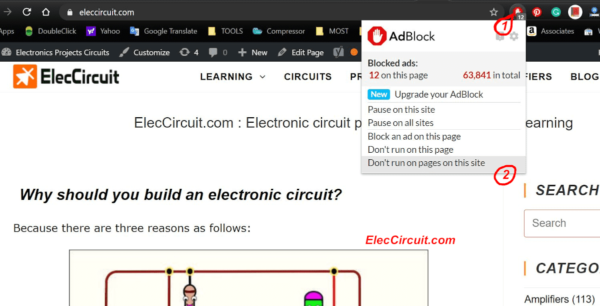
Showing these ads is part of what Empowers US.

Buy me a coffee
Another way to support what my children and I do is to Buy me a coffee 🙂
In addition, if you are a manufacturer or distributor of electronic products. We welcome any donation of those tools or products. Of course, it will benefit everyone. Because we will use your products well. Please contact me by this email: [email protected]
Our ElecCircuit Team


I am a single dad with 2 children—my son and daughter.

We’re Homeschooling.
Thank you very much for your support. To keep the site running.
Hi;
I want a battery monitor circuit that have three LED red,yellow and green.
When battery votlage is below 3.4V the red LED glows only,when battery votlage is above 3.4V red and yellow glows and when battery reach to 4.1V red,yellow and green LED goes on so please suggest a circuit.Reply soon
@phuoc
Thanks for tell me
It correct, please see the pcb.
@Daniel
Hi,
Thank for your comment I like it.
This circuit so old I sorry for not clear , I am new.
Please wait for me to write this article from my book.
@Faizan
Hi, I happy for you post if you still need this circuit please check these
https://www.eleccircuit.com/integrated-battery-level-indicator-with-3-level-led/
https://www.eleccircuit.com/many-logic-probe-circuit-ideas/
https://www.eleccircuit.com/the-led-display-voltmeter-in-probe-model/
If it helps you, I will be very happy.
Dearest momename,
your website is very interesting and potentialy useful, and your efforts and hard work are obvious. Personally I’m still learning much about component level electronic circuitry, and the explanations and descriptions are vital. It is obvious that you struggle with english, or at least your translator does. You might consider posting in english and another language which you speak fluently and can make accurate and helpful remarks in. Just let us know.
Thank-you for your site, and best wishes.
Hi @Gary D
Thanks to the impressive site.It is hard work. When using English, I needed translated into English. (You are correct.) I tried to use plain English style. Easier to read.
I feel uncomfortable. My site is very slow. Because, my poor English. I appreciate everyone’s interest. It is very driving force.
Thank-you for your comment, and best wishes too.
Thanks for all the (mostly useful) stuff you put on this website! It is greatly appreciated 🙂
Dear friend,
Indeed your venture is most appreciable. language Long live and wish u all success in your all ventures.
G.N.nataraj
Dear Sir,,,, I Understand You Perfectly!!! Your Circuits Are Awesome and I Love Your Site!!! Best Regards From Canada And MR.OHM!!!!Momename You Are GREAT!!!
So Many Projects Here and So Little Time To Build Them All!!! Many Thanks From MR.OHM 1970 for all Your Efforts!!!
Last week there was workshop by efy kits
but the concept was not clear, now aftr seeing your forum it is very useful. can someone tell me how simple wireless controll robot work?
Hi, I have a older Honda motorcycle that is running on a 6v system. Would it be possible to run a 12v dc lighting circuit using a step up transformer? Or is there a better way to go?
I would be very thankful for any information or ideas that you may have. Thank you
hi sir,i’m verry happy with your site,coz i’m hobby electronic. From indonesia. Thank’s very much
Hi Momename,
i read your articles,very interesting.
i want variable 0-130 voltDC supply. with input
230 volt AC.DC supply can be raise or lower by
small motor. can you give me circuit for this.
Punam shah
I have been using your web site for about two years and think you are doing a fine job.Keep up the good work.By the way your english is quite good. Thank you,JON.
Hi, JON NOLAN.
We very very happy to read you sound.
Thanks for power to us.
We will keep up this job all times.
dear sir
i am sangle vikas studied in e&tc 3rd year engg. I need your help regardingdelta modulation circuit diagram and component with specification.
i would be highly obliged if grant me your help.
Hi to you!
Your site is a great project which certainly is interessting for many people.
Don’t bother about your English.
Hi,Georg
Thanks for your power to me.
Many times some people comment my English very poor.
But I will keep this job.
And Now I so happy.
My son like it and will make this as successor indefinitely.
could u plss get any circuit for 2.1ch amplifier
Can’nt ? texs in indonesions language, please..thanks
Hi sir i am the student of electronic and commnication enginnering in 2nd year
I want to say you that this site is fantistic
i want some tips to you for my mini projuct
Watching your so called pro-amps, you use a cheap schematic, which is available on a large of forums on inet and ain’t build pro at all.
It allmoest looks like you’re a novice yourself.
Can you help me to build a voltage drop down circuit of from 6 vdc to 3 vdc with minimum loss. I am working on a LED lamp circuit.
pleas i wont and i like learn easy electronic some projects pleas help me i think you can help me also my english are very very poor only wont good hart thank you muditha silva .
Greetings
Thank you for your site
Have a good work in this field as possible the circuits in your site
In which a programmingIC can be used for site
Thanks
Arbatani
iran
azarbaijan
tabriz
I’m sure someone would be prepared to run through your site and correct the English – it can be quite difficult to follow what you are saying sometimes.
Momename:
Wonderful circuits! Good diagrams!
Readers can figure out what you want to say–based on your English level. Keep reading lots of English books and your English will surely improve.
You are doing a good job!
Trevor
END
###
Hello, I am an apprentice in electronics and spend a simple circuit to delay the initiation of a relay.
can help me indicating one of your circuits?
Thanks for taking my call.
jose freitas
I want 2030 ic 4.1 circuit 4 mosfet
This is a good site. .Wonderful circuits. .u r helping us all.good luck.
hi i need a simple circuit for pulse generator edm.
this edm is a super drill.
please insert it power mosfet irfp460.
voltage is abut 120v in open.
this circuit should adjustiveable onpulse@ offpulse control.
thanks
Hej Momename. Jeg sidder her og har prøvet at lave en Amp med 2 stk tipl 575 og 52 + volt og 52 – volt. Jeg ville efterligne den gamle Amp som jeg havde engang en starmaker 8041 mixer og det er her du nok kan hjælpe mig. Den på + siden tager signal, ok og den i – går ampærerne fra – til basis. Jeg håber inderligt at du kan hjælpe mig.
Med Venlig Hilsen Ken Bjørn Nilsson.
TAK
plz provide us a reverse parking ckt using 555 …..
Really Brother u r doing a very very good job for the electronics hobbysists. Please keep it up & serve the mankind. GOD BLESS:::
Hi, Neeraj B.Lal
Thanks for your feedback we will keep this job.
Your English is easily understood, no need to apologize for it.
There are not enough people interested in electronics, your site helps the ones that are find useful projects.
Thanks
Hi Gray,
Thank you very very much.
Today we very happy,hear you say that.
My wife love me that write English, people can read understand.
Great site! I really like the DC pwr supply and charging/converter circuits. You have good diagrams, and explain things well. Not only how, but WHY. Your English is fine with me. Keep up the good work! Thanks from Michigan
Hi Momename,I like your easy electronics site, please carry on.
Thanks From; Charles
sir 4 water sensor alarm using LM380,which type of sensor is required pls tell me
Hi there,
thanks for this awesome collection of circuits. It is instructive and useful and your English is absolutely sufficient.
Best wishes from Germany,
Georg
Hi Georg,
Thanks for your feedback. I will keep my job because useful for everyone.
I’m happy you can read my English.
I want to use variable to adjust output volt. I want to use output from 3V DC to 12V DC with load of 0.5 amp to 5 amp. I have used 10K to 500K variable but they are burning up in seconds. Please advice
12 volt DC dimmer circuit using variable is what I required.
Hi,
I purchased the automatic off 12v battery charger circuit from your site through paypal. I could download the pdf document but all is striked out. please send me clear document.
Thanks.
Hi Anandalal,
Thank you, I send e-book to your email again.
Hi, Its regarding Professional Solid State Relay,can you pls advise Price of PCB&resistor/cap ratings.
Have question on camera ccd. The wires had a pcb circuit but it fried how can I make a new one to be able to use cameras still.
sir i want built 1 kw 24 Vdc 40 Amps Mppt inverter can i get pcb with assembles ready, and i want know what is price, how much quantity i place.
with regards
shambu ss
mobile no:-09448125319
Hello
Nice site and useful to both beginners and professionals. Just wanted to check if you can send me PCB of a few projects you have described. I live in Chennai, India. Look forward to hearing from you. Will pay for PCB + shipping.
Great work.
W Vijay Kumar
Mob +91 9962 477 684
Hi. I am interested in electronic.
I really want to know how does circuit work and how to make circuit precisely.
I majored in electronics in university
But my electronic skill not enough to understand complex circuit.
Would you let me know how i have to study electronic to be expert about electronic?
Excuse me sir,
How to make dual led flasher using 5 volt with variable resistor. Can you help me please sir.
Thank you sir.
Sir, I want AC live detector circuits for using high voltage detection I did a circuit by using IC4017 it was working successfully but I need for Over head lines like 33/11kv to detect from ground on words In electricity dept..so many were dying due not traseing out the live supply I kindly request u to give us different circuits to help such people in working high voltage organizations thank u
Dear Sir;
My question is why do we need the Minus voltage? we see sometimes power supply equipped – minus & + plus voltage, for instant like the computer power supply.
thanks in advance.
Good Day..I am kindly request for quotation for this items please I need them
1.Regulated power supply Dual 0-30V
2.Decade resistance box DRB 0-10K
3.Function Generator 0-10MHz
4.Decade inductance box 0-100mH
5.CRO 0-30MHz
Hi.how are you?I seeking a good frind in electronic.Im in iran .do you pleasure?excuse me my english language is not good.i saw you in web(electcircuit).where are you from?thanks.
Please let me know u r in chennai
I need many projects
pls mail me
I need a quote for the 4 sound effect osc
Hello, I am just trying to build the circuit “Digital multimeter circuit using ICL7107”
A hex inversion buffer “CD 4049” (IC 3) is used. In the circuit, however, the component is probably misrepresented, or the name has been confused. Thus pin 16 is not used in the original (nc), but is connected. In addition, almost all outputs are interconnected, but no input is connected. Can you correct this circuit?
regards
Good day sir,mam
I have look on your side ,but I can not find a simple amplifere for MC to MD input for aplifire
( the drawing ,project dont must have RIAA becaus im just it to the input from MD phone.
The circuit must have only : low nois , lowist deformation.( and chaep afcorse)
I hoop that you me unterstood .
Thanks in advance for your time and replay
Cor Rotterdam Holland
PS your email adres Yahoo don’t work or Exists ( myn enlische is more ferry poor)
what can I do to be able to read a circuit diagram and understand.
Hello, Boateng Jodeph
I recommend as I understand. The circuit diagram is a combination of parts.
First, we need to understand the behavior of the device.
Second, see the working sequence.
Third, the big circuit comes from many small circuits. Do not need to worry about them.
However, I like the little circuit than the big circuit.
I believe that if you always use them. You need to understand them surely.