This AM receiver circuit with an earphone is a saving version that uses a few parts, cheap, easy to build, and Suitable to be assembled to study.
We come to understand the principles of the AM radio before. The Radio can receive radio wave signals. It also should have a radio frequency transmission station.
Basic AM receiver Working
The station does not send out the a sound wave that we talked. The station will produce the kind of wave called a carrier wave. This carrier wave conductor of sound waves that we listened to our radio receivers.
Read also:
The station must be mixed between the carrier and sound waves before. By this sound, we convert as an electrical signal by the microphone. Then, the signals mixed the signal together by the height of the wave. The height of the waves is not constant. But frequency is fixed see Figure 1.
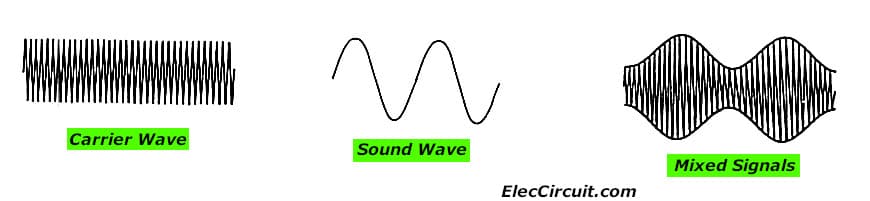
Figure 1 The characteristics mixing waves on AM radio system.
The Wave that mixed. It will be sent out by the station’s antenna.
We will use this system for AM radio receivers only. And we can choose the frequency of each station with simple. This behavior as shown in Figure 1.
The signal is selected by the receiver. The waves will be forwarded to the sector’s expansion wave.
Recommended:
- Simple Two Transistors AM Transmitter Circuit
- 3 circuits of guitar fuzz box and fader control
- Simple function generator using op amp LM1458
Which is responsible for the signal to be strong enough to use it. The increased wave section may have several sectors. When the signal is sent through the increased wave section, it will into the separate wave sectors.
Which act separated the carrier wave signal from the audio signal. This signal is Characteristics of the same signal from the microphone of a radio station.
Then, we can increase it louder with the Amplifier in order. To have the strength enough to use with headphones or speakers.
Technical information
- Use a power supply of 3 Vdc.
- Maximum consumption current about 45 mA
- PCB size : 2.38 x 1.24 inch.
How does AM radio receiver circuit works
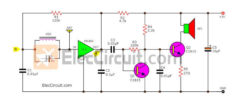
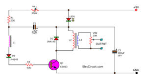
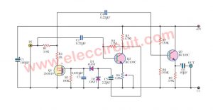
A circuit diagram is shown in Figure 1. The IC1 MK484 acts as the receiver system by have a variable capacitor and OSC coil as frequency adjusting of each station.
The IC’s OUTPUT will be connected to C3 to increase signal up by TR1 and TR2 sent to speaker.
Figure 1 the schematic diagram of AM radio receiver circuit
We use the general AM variable, The output is connected to dynamic headphones or also small speakers. But impedance to 30 ohms up. The ANT point for the antenna.
Testing
The connecting to speaker SP point. Then apply 3V DC power supply to the circuit. The positive polarity to +3V point and the negative polarity to the G. Then we will hear sound on the earphone.
Radio station signal. But if you can receive a few stations. You can adjust the OSC coil and move ANT to the antenna.
How to build
This project has a few we can assemble them on a universal PCB or solder on PCB as components layout and wiring in Figure 2
Figure 2 the components layout and wiring.
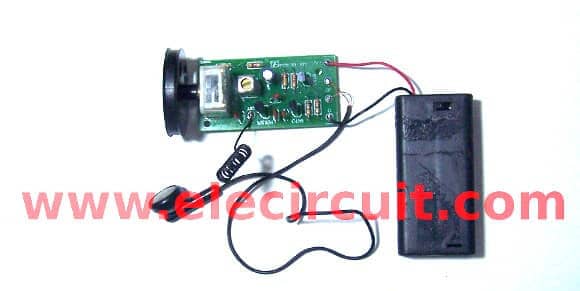
and Figure 3 is complete projects
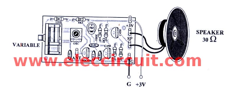
Figure 3 The AM simplify radio ready to application.
The parts list
R1: 120K
R2: 4.7K
R3: 220K
R4: 2.2K
R5: 27 ohm
Ceramic Capacitors
C1, C3, C4: 0.01uF(103)
C2: 104 or 0.1uF(104)
Electrolytic Capacitors
C5: 10uF
Semiconductors
IC1: MK484 or TA7642
TRANSISTORs
Q1, Q22: 01A 40V NPN transistor, C458, C828, C945, C1815
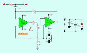
Simple AGC circuit (Bonus)
The automatic Gian control circuit also AGC with an audio signal is simplest for compress to signal in the Radio receiver. It is ideal for short wave radio receiver in areas with weak signals.
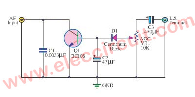
You should adjust the master volume control dress until the desired signal intensity. While tuning the receiver to the station light. Then, gradually tuned to the power station and adjust the AGC pot. Until then voltage in the hearing as needed.
Read next:
- Understanding Electronics Block Diagrams with Example
- Morning sun alarm circuit using IC-4011
- FM receiver circuit with PCB
Related Posts

I love electronics. I have been learning about them through creating simple electronic circuits or small projects. And now I am also having my children do the same. Nevertheless, I hope you found the experiences we shared on this site useful and fulfilling.
is there a way this circuit can be reversed to conceive an AM transmitter?. thanks.
and please what is an estimate of the receivers range?
Hi,rasputin
Thanks for your feedback.
Please try it all MW rang radio.
It is a nice work I appreciate it
I would like do a short wave receiver using 3 or 4ransistors.
Hello Hesyn,
Thanks for your visit. The Short wave receiver is a great circuit. If I have that circuit. I will tell you. Did you get a subscribe email?
Thanks
Apichet