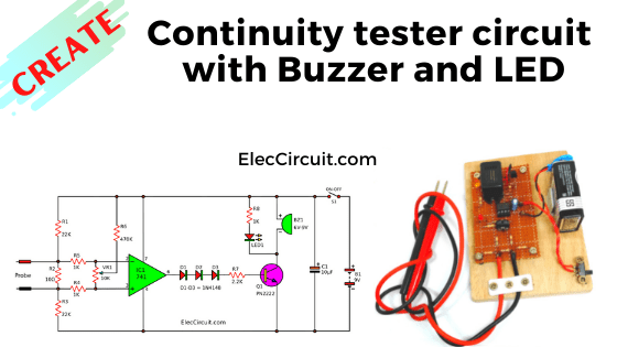
This is a continuity tester circuit with a buzzer and LED. Also, I like this circuit. Because unnecessary to take my eyes off the tested circuit. We will hear the buzzer and see LED glows.
Imagine, your circuit does not work, it might be due to solder joint defects. But it is quite hard to pinpoint. Where is the issue occurring? This tester circuit may become useful in this scenario.
The solder joint defects can consist of disconnect in PCB copper, solder bridge, floating lead, lacking solder, etc. Specifically, the increasing rate of human error because of the decrease in the size of electronic components. This problem affects us too.
The main condition of the circuit that we must think about:
- Emit sound and light to get results easily. Expected to use a mechanical buzzer and LED.
- Easy to build, be also an accurate and reliable circuit. Using an integrated circuit(IC) might be a better choice than transistors. We choose IC-741 because of meets the requirements and is cheap, too.
- Low power consumption, can be used with battery for a long time. We will use a 9V battery for this circuit.
Feature of this circuit
We have tested it and found this circuit has the good properties we want.
- Can work when the resistance between two probes is lower than 1Ω.
- Other components connected to the point currently tested, that have a resistance over 1Ω will not affect the testing.
- There is only 200uA and 2mV coming from two testing probes. It definitely does not hurt the circuit we are checking.
- Even if we measure across the semiconductor junctions (P-N), it would not affect the circuit.
Is it better than other continuity testers?
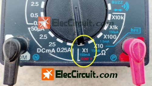
Some tools may damage the devices within the circuit we measure because it outputs current up to 150mA.
How is Continuity tester circuit work
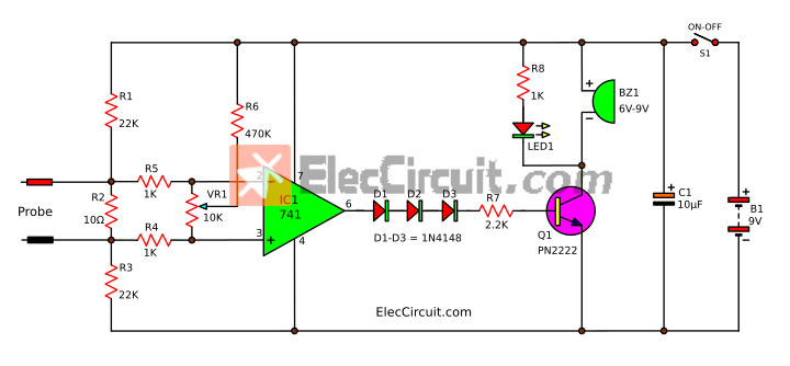
In this circuit below, we use a popular 741 IC as a high gain Op-amp.
The 741 op-amp has many details. If we will learn all of it now, it will cause this post to be too long. For now, we just want to create the circuit. So, we will only look into how to use 741.
See various pins we are using.
- Pin 7: Positive power supply
- Pin 4: Negative power supply
- Pin 6: The output
- Pin 2: The inverting input
- Pin 3: The Non-inverting input
741 comparator
The 741 is good at detecting a tiny amount of voltage.
So, we use it to compare a different voltage between the inverting and Non-inverting input. That difference voltage got increased to be sent to the output. This is called the op-amp comparator.
According to the condition above, we want a probe that can check a resistance under 1 ohm to cause the output to be “high”.
See the circuit, the input section should be a voltage divider with a resistor network. The electric current flows through R1, R2, and R3.
Normally, the voltage across R2 is at some value. But if the resistance across R2 is lower than 1 ohm, the voltage across it is also lower.
Some current comes in the Op-amp’s input through R4. R5.
In principle:
The output voltage is “high” when the voltage of the non-inverting input is higher than the inverting input.
So, we use R2 to protect the output not to be the negative voltage because the inverting input has a higher voltage than non-inverting.
And, the voltage of non-inverting input can be increased by adjusting the VR1, which will result in the positive voltage at the op-amp’s output.
Connecting buzzer and LED
We can not connect the buzzer and LED to the output directly. Because the output current is too low. And from our experiments, the output voltage is unsuitable for this usage.
The testing process
If the probe receives resistance higher than 1 ohm, the output will be about 1.9V (low state). On the other hand, if resistance is lower than 1ohm, the output will be 6.5V (high state).
We should set the voltage at the “low” state to about 0V and the “high” state to around the power supply voltage (9V).
This issue can be solved by adding to our circuit; 3 diodes connected in series. They will block all of the low state voltage (1.9V) making the low state absolute 0V.
But in the high state, the current can still be passing through to the R7, and Base to Emitter of Q1. Causing Q1 to conduct a larger current from the power supply to power the Buzzer and LED.
Recycling free white SMD LED from e-waste
How to build and set the circuit
This circuit has quite a few components. So, we can assemble them on the perforated PCB easily.
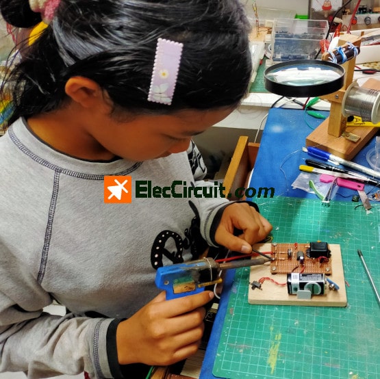
We are making the prototype of the continuity tester circuit using 741.
Recommended: If you are a beginner, read Electronic components list with images.
How to set and test
Here is a step-by-step quickly setting.
- Take a 1-ohm resistor to test it on the probes.
- Adjust VR1 until the buzzer emits and the LED glows.
- Check it with a 2.2 ohms resistor, the buzzer should have no sound and no light.
- Test it with other PCBs and wires.
Parts list
0.25W metal/carbon film Resistors, tolerance: 5%
- R1, R3: 22K
- R2: 10Ω
- R4, R5, R8: 1K
- R6: 470K
- R7: 2.2K
Semiconductors:
- IC1: LM741 or UA741 or HA1741 or Equivalent
- Q1: PN2222 or 2N3904 or S9013
- D1-D3: 1N4148, 75V 150mA, Silicon Diode
- C1: 10uF 16V Electrolytic capacitor
- LED1: 5mm LED, any color
Others
- C1: 10uF 16V Electrolytic capacitor
- BZ1: Mechanical buzzer, 6V-9V
- S1: On-off small slide Switch
- B1: 9V battery with snap battery Or 9V power supply circuit
- PCB, Wires, others
We like this tool because it has high efficiency, and meets the needs. Most importantly, we built it ourselves, cheap! What do you think?
You may also like these circuits
- How to test a diode without meter
- Battery voltage monitor circuit using LM339
- The Op-amp IC tester circuit
Download This Post
All full-size images and PDFs of this post are in this Ebook below. Please support me. 🙂

GET UPDATE VIA EMAIL
I always try to make Electronics Learning Easy.
Related Posts


I love electronics. I have been learning about them through creating simple electronic circuits or small projects. And now I am also having my children do the same. Nevertheless, I hope you found the experiences we shared on this site useful and fulfilling.
Nice project, however have a problem with my circuit – done the setup routine and led remains on, not very bright when I test on a 1 ohm resistor led will go brighter buzzer will sound , can you please help, don’t have pn transistor, using a 2N3904 and 2N2222 with a LM741 thanks Chris From the UK.
Hi, Chris
You can use a 2N3904 or 2N2222 transistor.
Please calm down and recheck the circuit. It may have some components in the wrong position. You may check the Resistor network in the input section and adjust VR1 as well.
Thanks
Apichet
i think probe tester no use. supply on buzzer and led already on. then where the function of pcb as continuity tester? how the probe can react to test continuity if in low voltage?
Hello, my dear friend,
Thanks for your visit to our site.
This is a feature of this circuit: https://www.eleccircuit.com/continuity-tester-circuit-with-buzzer-and-led/#Feature_of_this_circuit
Yes, we can use this tool for testing continuity with low voltage or without the source.
https://www.eleccircuit.com/continuity-tester-circuit-with-buzzer-and-led/#How_is_Continuity_tester_circuit_work
God bless you.