Let’s play with a simple toy organ circuit. A daughter of mine has interested in piano. But at the moment we are unready to study it. Believe it or not, we can create a simple piano circuit by ourselves. It reminds me of this organ circuit, that I made when I was a kid.
But now I will use this to teach my daughter about simple electronics and have a fun time together.
What is a toy organ?
A toy organ circuit or a monophonic organ is a circuit that generates tones according to the pressing of a key. The button can only be pressed one at a time.
How does it work
This circuit generates the sound frequency in a way of an astable multivibrator. We are familiar with this sort of circuit from the two LED flasher circuit.
Basic thought
Suppose we connect a loud speaker with an LED. We will hear the “Tik…Tik” sound as LED flashing. And when we increase the speed which the LED flashing. The continuity of the sound we hear will increase to the point of becoming a normal buzzer.
See the simple sound frequency generator circuit below.
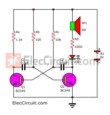
The tone level or frequency is based on C1, C2, and Rb, Rc. In terms of a simple circuit design. We better change Rb and Rc. If we leave Rb alone and instead modify Rc, it will also change the tone.
Which Rc can be controlled by the keypad. We need 7 different tones for 7 different keypads. So, let’s take a look at the simple push-button circuit.
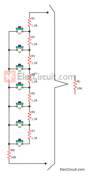
These set of resistor and switch represent Rc in the first circuit above
Learn: series circuit
They work as follows.
If we press the button S1 the current will flow through R1, S1 to R8 in series. Making total resistance equal to R1 + R8 (1.2K + 10K) = 11.2K.
But when S5 is pressed the current will flow through R1, R2, R3, R4, R5, and S5 to R8. So, total resistances equal to (1.2K + 1.2K + 1.2K + 1.2K + 1.2K + 10K) = 16K.
To sum up, the total resistance will take account of each resistor it passed, plus R8.
Of course, the lower the resistance, the higher the frequency, and vice versa.
Recommended: 1.5V 4 LEDs Flasher circuit using transistors
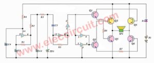
How toy organ circuit works
Now, let’s look at the whole circuit as shown below. And understand the working principle of this circuit as a high-frequency generator circuit.
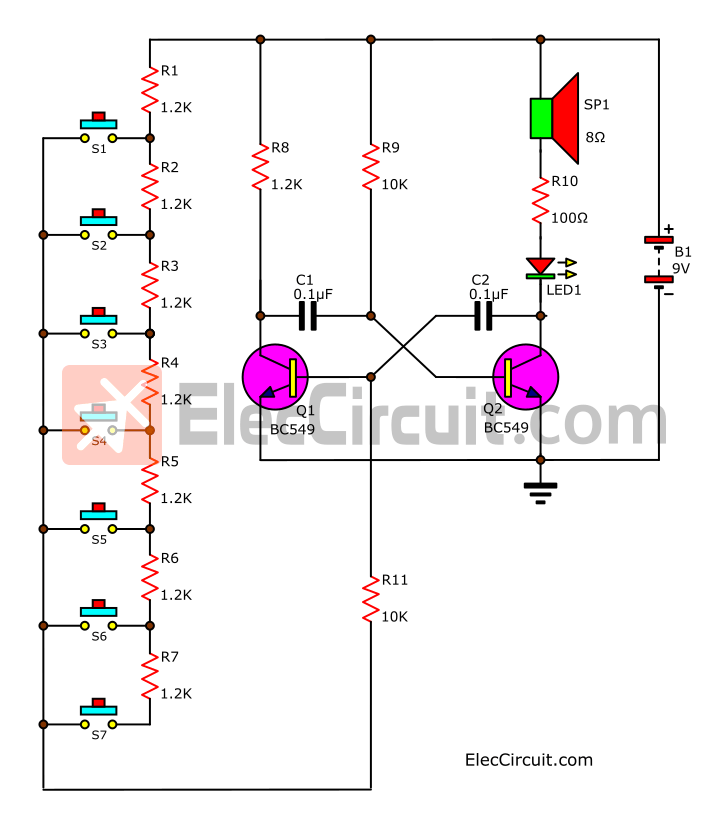
When we power this circuit, it would not do anything right away. But if we press switch S1, the circuit will begin the work. By having the current flow through R9 into B of Q2. It makes Q2 begin the work first, making the current flow through SP1, R10, and LED1.
By pressing S1 for a few seconds, causing the current to flow through R1, S1, R11, and charge the C2 until fully charged.
Then, Q1 will start to work, letting the current flow through R8 to C1. And charging it to lower the bias voltage at Q2 until it stopped working. Right now the LED1 will go out indicating that there will be no current flow to SP1.
When the C1 is fully charged the current will flow to B of Q2. Causing Q2 to start up again, and Q1 will stop working. They will continue to work alternately like this, creating frequency in the process.
If we press on other switches the total resistance will change depending on the number of resistors as we have talked about before.
How to build it
Let’s assemble this simple toy organ circuit on the breadboard first, to easily visualize its working process.
Note: We can use many small NPN transistors but they are different legs pinout.
Check out these transistors on Amazon
The parts list
0.25W metal/carbon film Resistors, tolerance: 5%, (Unless stated otherwise)
R1-R8: 1.2K
R9, R11: 10K
R10: 100Ω
Ceramic or Mylar Capacitors
C1: 0.1µF 50V
Semiconductors:
Q1, Q2: BC549 or equivalent, 45V 0.1A, TO-92 NPN Transistor
LED1: 3mm Red LED
Others
SP1: Lound speaker 8Ω – 16Ω
S1-S2: Push-button switches
B1: 9V battery and snap connector Or 9V power supply circuit
Breadboard
Download This Post
All full-size images and PDFs of this post are in this Ebook below. Please support me. 🙂
GET UPDATE VIA EMAIL
I always try to make Electronics Learning Easy.
Related Posts


I love electronics. I have been learning about them through creating simple electronic circuits or small projects. And now I am also having my children do the same. Nevertheless, I hope you found the experiences we shared on this site useful and fulfilling.
hi,thank for your good site. i need more information for make this circuit. please help me!
Please answer me quickly. i’m waiting for your email. just quickly quickly quickly pleaseeee …. 🙁
thank you .. 😡
How many ohms is R11?
220 Ohms is the resistor requirement for R11. Worked perfectly for me
First of all I want to say great blog! I had a
quick question which I’d like to ask if you don’t mind.
I was curious to find out how you center yourself and
clear your thoughts prior to writing. I’ve had a hard time clearing my mind in getting my thoughts out.
I truly do take pleasure in writing but it just seems like the first 10
to 15 minutes are usually lost just trying to figure out how
to begin. Any suggestions or hints? Many thanks!
Does this circuit really work please some1 Respond!
I couldnt get this to work with 2N3904s or BC547s.
nice circuit man, my father made a circuit like this, it easy and fun.
Thanks for your feedback.
Another. Great circuit!!!!! Thanks!!!!!
Hi, my friend Thanks for your feedback.
Have a great day.
Es bueno para los niños, pero 555 fichas son mejores.
Hello JJ
Thanks for your opinion.
many thanks for this terrific. Site!!!
Thanks, my friend!
many thanks for this terrific. Site!!!