Do you know a signal injector circuit? It can be a tool or accessory for repairing television or radio receivers, amplifiers, etc. It will produce a small-frequency signal. It uses a 1.5V battery power supply.
This circuit is small, has few components, and is therefore easy to build.
For example, we are going to repair an amplifier when we feed it an audio signal with this simple circuit. If the amplifier is normal, we will immediately hear a loud sound coming out of the speaker.
Even checking signals at various points with an oscilloscope is easy. We can use it to check the vertical yoke driver of the old TV, or we can use it for many other applications.
Are you starting to get interested?
If you would like to support us, you can buy me a coffee.

How Signal Injector Circuit Works
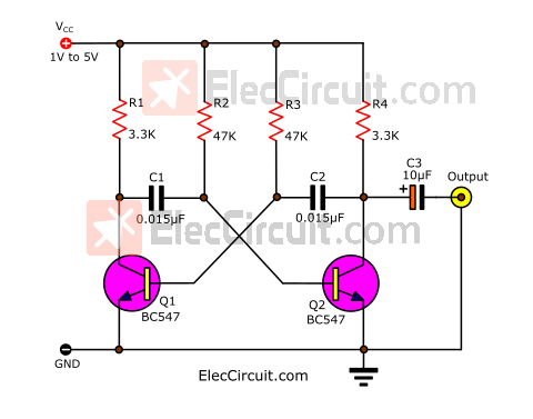
In a simple signal injector circuit, as shown below, we used two transistors joined together to create an astable multivibrator form. The output is a pulse signal in a square waveform of about 1,000 Hz.
Read also: How does a transistor circuit work
The power supply voltage of this circuit is 1V to 5V. We recommend a AAA 1.5V battery; it makes the level amplitude voltage peak at the output lower than 1.2Vp-p. It is quite suitable for experimenting with general circuits such as amplifiers, radio receivers, and so on.
Creating this circuit
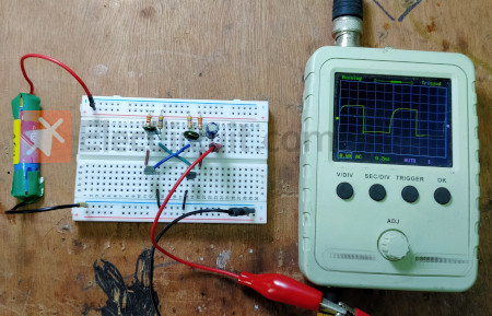
My daughter assembled this circuit on a breadboard and used a scope to examine its signal. There is a relatively square waveform signal with an amplitude of approximately 1.3 Vp-p at a frequency of approximately 856 Hz, close to 1 kHz.
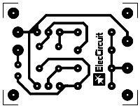
If you really want to use it, you might build the PCB below. It was easy to create this project.
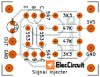
How to Builds.
The Copper PCB layout and The components layout
You can see the PCB layout and the components layout in above cause you builds easily this projects.
Parts will you need
Q1,Q2: BC548, BC547, BC549, 2N3904, 45V 100mA NPN Transistor
C1,C2: 0.015uF 50V, Ceramic Capacitor
C3: 10uF 25V, Electrolytic Capacitors
R1,R4: 3.3K, 0.25W Resistors tolerance: 5%
R2,R3: 47K, 0.25W Resistors tolerance: 5%
And others.
Recommended: If you are a beginner, read Electronic components list with images.
Conclusion:
Although this circuit is simple, it may make your work easier. It may also help in learning more about other electronic circuits. In addition, we may try to create circuits related to other measuring devices.
GET UPDATE VIA EMAIL
I always try to make Electronics Learning Easy.

I love electronics. I have been learning about them through creating simple electronic circuits or small projects. And now I am also having my children do the same. Nevertheless, I hope you found the experiences we shared on this site useful and fulfilling.
What a Handy Dandy little Tester,,,Great for the Bench!!!
Useful piece of Test Gear,,,Thanks!!!
What a Handy Dandy piece of Test Gear to have around the Bench!!
This is a Real handy dandy piece Of test gear to have around the test Bench,,,Thanks!!!
how can i adjust dutycycle of this circuit
what is maximum frequancy of this circuit
Hi, Bhavesh
Thanks for your feedback.
Yes, you can change C1,C2 for setting frequency and duty cycle.
i have an audio component that was not working. brand National(AFD) Rx C51. i need circuit diagram all of this component. please help me.
thanks