This is a 4 transistor audio amplifier circuit. Which is a 4-transistors complementary push-pull amplifier, that shows the basics of audio amplifier design.
This circuit saving on battery current, which is quite low with middle volume, rising to 25 -30mA as a volume is increased.
This gives us a 250 mW amplifier, enough to drive a loudspeaker to the same volume as a mobile phone or MP3 player.
The input must be about 100-500 mV to drive amplifier fully. Previously, you may like LM386 amplifier circuit. But you may also like this circuit as well.
The working of 4 transistor amplifier circuit
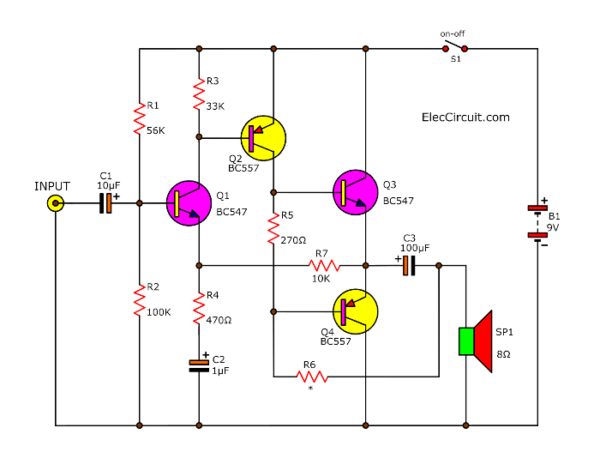
This type of circuit using few components needs no transformers and provides very good results. The 4 transistors are directly coupled and DC feedback loops help stabilize the working of the circuit.
Recommended: Learn transistor works here
4 transistors working
Both transistors Q3 and Q4 are arranged as a complementary pair operating in push-pull. Each output transistor deals with one half of the audio cycle, one being cut-off when the other conduct.
Next, the Q1 and Q2 transistors run as a pre-amp to increase the incoming voltage to drive the output pair.
Then, at Q1 the bias of the whole circuit commences with the voltage divider made up of the 56K and 100K resistors.
This provides the base with a bias voltage of 5.5V. The emitter voltage of 0.6V less than this, and will be 4.9V.
And next, The Q2-transistor is biased so that it provides a voltage across the 270 ohms load resistor, which will give the output transistors.
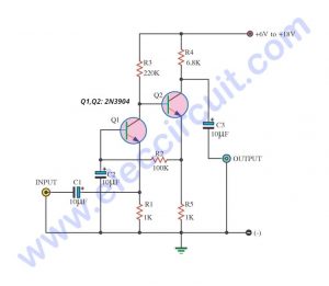
Recommended: 3 transistor audio amplifier circuit
There is a voltage differential of 0.6V between their base and emitter leads.
This needs to reduce cross-over distortion which occurs whenever two transistors are connected in push-pull.
The 100uF electrolytic protect DC from appearing on the speaker, the require the speaker to oscillate around this new position.
See many transistor amplifier circuits
First of all, You need all parts below
Parts you will needs
- Q1,Q3: BC547 or equivalent, 45V 0.1A, NPN Transistor
- Q2,Q4: BC557 or equivalent, 45V 0.1A, PNP Transistor
0.25W Resistors tolerance: 5%
- R1: 56K
- R2: 100K
- R3: 33K
- R4: 470 ohms
- R5: 270 ohms
- R6: 1.5K
- R7: 10K
Electrolytic Capacitors
- C1: 10µF 25V
- C2: 1µF 25V
- C3: 100µF 25V
- B1: 9-volt batteries Or 9V power supply circuit
- SP1:8 ohms 0.25” Speaker
This circuit requires enough power supply. Do you have this one? If you do not have it. Look:A lot of Power supply circuit
Build the 9V mini amplifier
This circuit is a small size you can assemble them on the breadboard. Or You can assemble the amplifier circuit on A small piece of universal PCB Board 20 – 25 holes. Make a layout diagram first which very nearly follows the schematic diagram before attempting any soldering.
With care you will find you will not have to cut any of the universal PCB Board tracks and most the parts will fit neatly onto the board as they all 0.1” spacing.
For my son plan will build it on wood board or hard paper it also saving money and fun amazing!
When you complete soldering, Next, connect the battery via a milli-ammeter to check, that the current is within 30mA and most probably is 5-15mA with no input signal.
You may like to trace through the amplifier with the signal tracer project.
Obviously, all the step cannot provide the good amplifier, since a transistor has a gain of at least 20 times, and sometimes an in-circuit gain of 100.
Thus, this gain of amplifier about 20 x 20 x 20 or 8,000 times! But this is not so. If the input about 250mV, the amplifier needs to provide a gain of about 40 to 80 times.
Your signal tracer will indicate which transistor is providing this gain. See for yourself. In all, these combined 4 transistors projects should give you hours of fun. Although, this 4 transistor audio amplifier circuit is ancient, it still suitable for children’s learning and good sound.
Source:http://www.talkingelectronics.com/
If this circuit gives you too little power. See the circuit below.
5 watts 4 transistors Booster Circuit
This is a 5 watts Audio Booster circuit using 4 transistor. From 4 transistor amplifier above. Let’s look at this circuit. The sound is definitely louder. We change some devices and increase the supply voltage level. Which can increase the power for a speaker by about 4 to 6 watts.
This circuit is quite ancient. It was also used as a booster circuit for cassette radio receivers. It has a frequency response of 44Hz to 33,100Hz, can accept an input signal of up to 1 Vp-p, and is suitable for the power supplies of 18V to 22V.
How does it works
First see INPUT stage, Q1 acts as a voltage amplifier in direct coupling mode.
Second, DRIVER stage, Q2 is connected with the common-emitter, and directly connect with Complementary common-collector amplifier by Q3 and Q4.
Third, the OUTPUT stage Q3 and Q4 will be a negative feedback, causing 100% feedback, thus the DC gain ratio is 1.
Then, see R1, R2 and R6 are voltage divider circuit. To bias the base pin of Q1. Thus, The base voltage of Q1 will be about half of the supply voltage.
This is approximately equal to the output voltage as well. Because the D.C. gain is 1. This allows for maximum output signal swing without a hard clipping.
The R7 and C9 are used to the decoupling in sound frequency range.
Use D1 for biasing the pair of output transistors. To reduce crossover distortion.
Moreover, Q3 and Q4 are the following emitters. It will make the output impedance is low. So, It can drive load is the speaker with high current.
Q3 is activated on the positive half of the signal and Q4 is activated on the negative half.
If the output signal of the positive and negative side is not completely synchronized. We will call it a cross over distortion
C3 and C8 will protect a DC signal on the input and output.
C1, R6, and C2 are power supplies with decoupling and noise reduction that may come into the power supply cord.
C5, C6, and C7 add stability to the circuit.
VR1 will act as a volume control.
The components list
0.25W Resistors, tolerance: 5%
R1, R2: 33K
R3: 1K
R4: 680Ω
R5: 100Ω 1W 5%
R6: 4.7K
R7: 39Ω
R8: 820Ω
VR1: 100KA Potentiometer
Electrolytic Capacitors
C1: 100µF 25V
C2: 220µF 25V
C3: 2.2µF 16V
C8: 2,200µF 25V
C9: 10µF 16V
Ceramic Capacitors
C4: 0.0012µF 50V
C5, C6: 82pF 50V
C7: 33pF 50V
Semiconductors:
Q1: 2SA561, 50V 0.15A, PNP TO-92 Transistor
Q2: 2N3053, 45V 1.5A, NPP TO-39 Transistor
Q3: TIP41, 100V 6A, NPN TO-220 transistor
Q4: TIP42, 100V 6A, PNP TO-220 transistor
***or equivalent
D1: 1N4148, 75V 150mA Diodes
How to build
You may try building this circuit on a breadboard first. See in Fig. below.
Or on Perforated PC board. You may also build it on the PCB as shown.
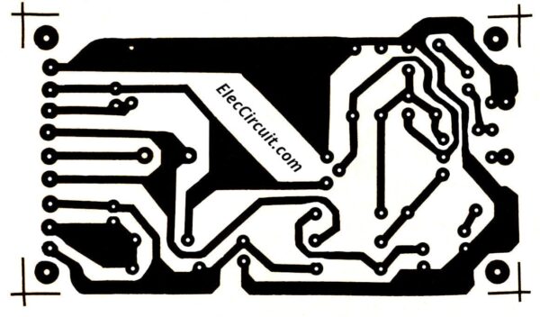
PCB layout
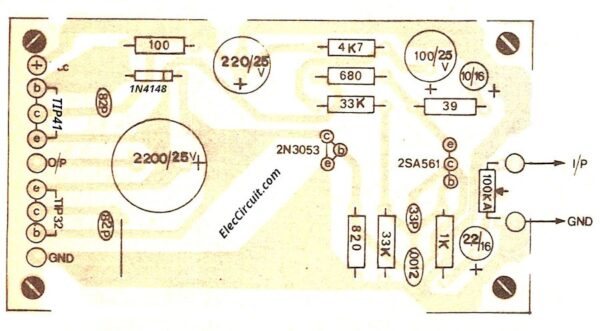
Components layout
Note:
- While using this circuit, Q2-2N3053 and R5 will get warm. Because there is current flowing through it all the time. and should use R5-100 ohms of 1 watts or more.
- Q2, Q3, Q4 should be installed on the appropriate heatsink.
- This circuit consumes about 1A of current and 18V to 22V of voltage.
Other transistor amplifier circuit
There are many amplifier circuits using transistors. You may like these circuits.
30-watt OCL amplifier circuit diagram with PCB using 2N3055
Imagine you want to listen to great music in your room. You may have many choices. Before seeing others. Let’s see this 30w amplifier circuit. Why you should see it? If your small room is small. And, you like to listen to great music that has nice quality, low noise, and full option adjusting. Also, it is cheap and easy to find the parts in any store. Read more: 30W OCL amplifier circuit diagram
Download This
All full-size images and PDFs of this post are in this Ebook below. Please support me. 🙂
GET UPDATE VIA EMAIL
I always try to make Electronics Learning Easy.
Related Posts

I love electronics. I have been learning about them through creating simple electronic circuits or small projects. And now I am also having my children do the same. Nevertheless, I hope you found the experiences we shared on this site useful and fulfilling.
Hocam
Gerçekten eğitici öğretici yazılar yayınlıyorsun başarılarının devamını dilerim…
Hi hakan
Yorumun için teşekkür ederim …
Thanks for your feedback.
Hi, I am trying to build this with friend at school for lab project, and we are having trouble getting the speaker to emit audio. We barely hear little audio at low frequency through function generator of myDAQ device. We are using all the parts necessary but we are not sure if there is something we are doing wrong or missing. How would we do this through myDAQ device?
Hello
Thanks for your visit. Oh…I am very very sorry. My son draws the circuit wrong.
I just redraw now. And if I have free time I will draw it on the breadboard.
Please see the circuit again.
Best regards,
Apichet
where the correct circuit?
Hello wira narendra,
I am glad that you were interested in this circuit. It worked, but it(simple circuit) may quite a little sound.
I am trying others circuit. It is louder sound.
Thanks
I apply a 100mV 1000Hz signal as the input signal (sine). When I connect an oscilloscope to the Output, the signal comes out clipped. I’m viewing a clipped square wave in the range of + 4.8V to -7.70.
My aim is to amplify waves with 100-200mV amplitude and 100-3000 Hz frequencies.
Hello Ahmet Eser, Thanks for your visit. I am happy that you are interested in this circuit. It may work well with input low impedance. I am sorry if it does not run for your work.
Please see others:
https://www.eleccircuit.com/fet-preamplifier-circuit/
https://www.eleccircuit.com/high-impedance-pre-amplifier/
I believe in you. You can build these circuits.
Thanks again.
Apichet
Hello. I am adding a Bluetooth receiver to an old boombox I have by tapping into its internal amp. the Bluetooth receiver has a headphone out jack that overpowers the amp in the radio and I’m assuming the impedance is too low from the Bluetooth out. if I use this circuit will it help match the signals and it will reduce the distortion? thank you.
A great way to learn about amplifiers, and good easy explanation of the circuit, thank you.
Hello,
Thank you for the circuits suggested. I tried the amplifier using two BC547 and two BC557 on a breadboard. The effect is very good except the noise when there is no input. Part of the noise seems to be from the power supply and I connect a 4700uF capacitor across it and improves a lot, but cannot remove the noise totally. I think using a breadboard with many connecting wires and carbon film resistors are other sources of noise. I will be constructing the circuit on a PCB with metal film resistors later.
Hello,
Your experience was great. I saw my dad experiment with this circuit. It is quite noisy. But the sound is not good. Compared with TDA2004, IC has better sound quality. But it’s probably reasonable. Because inside the IC there are many transistors and other circuits included in that IC. But transistor circuits are good for learning (even if they’re boring for me).
You got it right. If using a good power supply Can reduce noise I’ve tried it before.
In the future I will try to build an audio amplifier circuit that uses more transistors. It will have a good sound. I don’t like very loud noises. Because listening to music is so loud, Grandma always complains. LOL 🙂
Hello, it’s Desmond again.
I constructed the amplifier using TIP41C and TIP42C on a breadboard with a 19V supply from an old laptop. Its performance was very good. The 100 ohm resistor was very hot as expected and I plan to use a 5W one. However, the 2N3053 is very hot, even hotter than the TIP41C and TIP42C. Is it normal? If so, I plan to use another TIP41C to replace it. Would you have other suggestion? Thank you.
One more information: I use 2N2907 in place of 2SA561
Yes, you can try it.
Hello Desmond,
I am happy you are interested in these circuits. It is an easy old amplifier circuit.
It is quite old. Yes, there are high current flows in the 2N3053 transistor.
You may try BD139 and then install enough heatsink. or you may try the TIP41 to replace 2N3053.
I think this circuit is only suitable for beginners.
We may be able to learn about other circuits in the future.
I’ll try other circuits next time, but I’m not good at large amplifier circuits.
Thanks
Apichet