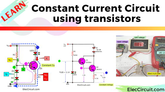
Here is a constant current circuit using transistors. Because the Ni-HM battery should only be charged with a constant current. Our friends need it.
Also, I and my daughter are interested in learning/trying out this circuit.
Normally the current will change always according to the voltage level. Imagine an LED display, when higher voltage, it gets a higher current, too. Of course, it can get damaged.
Learn first: transistor circuit
For the battery, when it runs out of power. Its internal voltage and resistance are very low. While charging, the current is very high. It causes by very high heat, which is not a good result at all.
Would it be better if charged with the constant current? The current flowing through it is low and constant. It doesn’t get hot, so it can be recharged many times.
If you would like to support us, you can buy me a coffee.

Basic Constant current circuit Learning
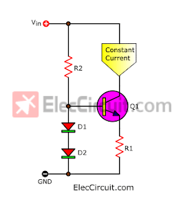
There are many types of constant current generator circuits. This time we choose to study a transistor circuit. It’s cheap and easy. Sure, we should start in a simple way. Look at below.
We believe that problems make the best learning. From; How to use easily LEDs. But the LED emits light unsteadily when used with a higher voltage source.
The LED needs constant current. For the voltage, it will be pulled up by itself, as required. When we keep the current constant. It will pull the voltage is almost constant. Of course, the light is more stable, too. Is this nature of LED true?
Let’s found out.
Experiment basic circuit
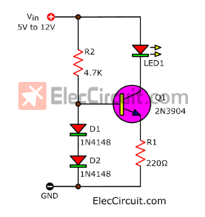
We try to set the condition to use the 3mm red LED again and a voltage source of 5V to 12V. From the basic circuit above, let’s choose the parts list.
- Q1: When we use the 3 mm LED, the voltage level is just like that. We can use any small NPN transistor, e.g. BC547, BC337, 2SC1815, 9013, 2N2222, etc. We use 2N3904. Note: Be careful with the different leg positions.
- R2: Bias current (IB) resistor to a transistor. We use 4.7K because of the low lC.
- D1, D2: We use 1N4148, this circuit requires low current.
- R1: It’s the most important Because it defines constant current to the load (LED).
We can easily calculate its value:
R = 0.7V ÷ I
We know I, is constant current, is ILED. The current lowest of LED is about 3mA(0.003A).
So, R1 = 0.7V ÷ 0.003A = 233Ω. But we use a 220Ω resistor.
Or see Shopping List:
0.25W Resistors, tolerance: 5%
- R2: 4.7K, Quantity: 1
- R1: 220Ω, Quantity: 1
Semiconductors
- Q1: 2N3904, 45V 0.1A, NPN TO-92 Transistor; Quantity: 1
- LED1: 3mm red LED; Quantity: 1
- D1: 1N4148, 75V 150mA Diodes; Quantity: 2
Then, look at the circuit diagram below. Even, fewer pieces of equipment. But it might seem confusing for beginners.
Assemble this circuit on a breadboard, and compare the results when we change input voltage, between 5V to 12V. Notice the LED, it’s steadily bright. Great!
If you still don’t understand clearly, try reading this: Electronics for beginners
Measure the current of the LED. It is constant at 2mA in all voltage ranges. And measuring the LED voltage is 1.9V constant as well. See the illustration below.
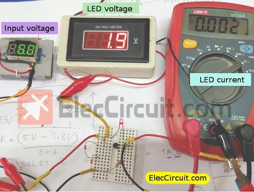
Note: The meter gets less precise than the calculated formula a bit.
Why current is constant?
Now coming to the difficult, I have a big question: how to explain the operation of the circuit in a simple way? until my daughter understands. This content may not be suitable for people who like complex principles.
Here are some facts that you should understand for yourself.
When the voltage and resistance are constant, the current is surely constant. This can be confusing. Look at the circuit again.
See flowing current
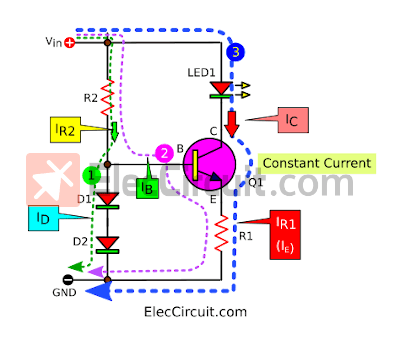
- No 1: a little current flows through R2, D1, and D2 to GND.
- No2: while some currents flow through R2 to B pin and E pin of the transistor, and R1 to GND, too. It is a bias current to the transistor. We call it that IB. So, Q1 conducts. And,
- No 3: Making a large current flows through LED to C pin and E of the transistor, the R1 to GND, as well. Thus, LED glows.
We will see that: IC of transistor = ILED, while IE is IR1. From principle: IE = IC + IB, but because the IB is very small. We may ignore it as IE = IC (almost the same). In conclusion, ILED = IR1.
We’re going to link it to find out.
The voltage at different points
What’s more. Meare a voltage at various points.
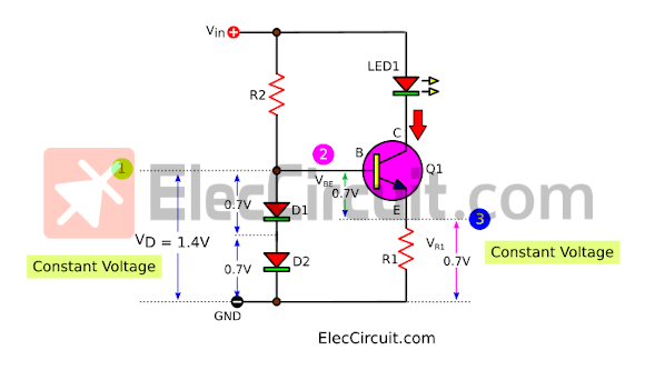
1. VD—D1, D2
There is a constant voltage drop across both diodes of approximately 1.4V. Each diode has a voltage drop of about 0.7V. While is Vin 5V to 12V range. Why?
The principle is: that when a little forward current flows through the diodes. It will conduct when the forward voltage reaches a certain threshold point. For Silicon diode is 0.6-0.7V.
It will maintain the voltage level while it is still conducting.
2. VBE and VR1
Look at the above illustration circuit. Both diodes D1-D2 are across B-E of transistor and R1. Sure, they are also forced to keep the voltage constant,1.4V. Then,
- The internal structure of the transistor between the B-E pin is like a diode. So, the voltage across B-E is 0.7V.
- Thus, the voltage at R1 is 0.7V (constant as well) So we can easily link to calculate the formula above.
R1 = 0.7V ÷ ILED
In conclusion, when VR1 is fixed at 0.7V. So, the ILED (load) is stable too, meeting our goal.
Recommended: Simple Li-ion Battery Charger Circuit with Automatic Cut-Off
Make Ni-MH battery charger circuit
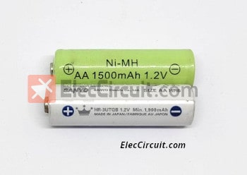
We have learned enough about the constant current circuit using transistors. Let’s make a Ni-MH battery charger circuit. Currently, the Ni-MH battery has more capacity more than 1500mA or 1900mA, high efficiency.
Next, let’s see how to choose the right devices.
- We should charging current—ICharging about 0.1C or capacity battery x 0.1 = 1900mA x 0.1 = 190mA. We set it about 170mA.
- Sure, a small transistor cannot get it. We need to use a larger one.
- There be should LED display battery are charging.
- Easy same above circuit.
Look at the circuit diagram below.
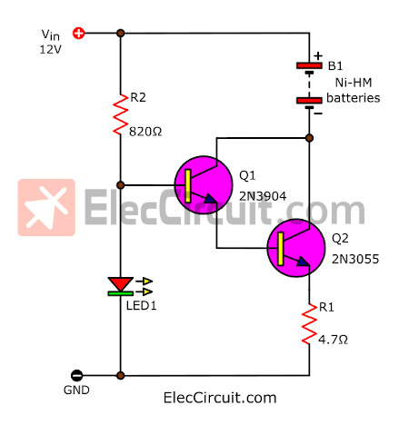
- Change D1, and D2 into a LED. Also, It can keep a stable voltage. Besides, It indicates battery connecting.
- Put another power transistor—Q2-2N3055, to deliver 170mA of output current. Also, we put Q1 and Q2 in Darlington pair form, causing have high gain to drive the load.
Note: You may use TIP41, MJE3055, and more. They are smaller than one, on TO-220. But I love 2N3055, it is more durable and has high performance. - Calculate the value of R1 = 0.8V/ICharging = 0.8V/0.17A = 4.7Ω. And, Power = V x I = 0.8V x 0.17A = 0.13W, or use 0.25W resistor.
- Use LED1 as a 5mm Green LED. It will keep a voltage at about 2.1V and be stable, too.
See other simple electronic circuits
Then, assemble this circuit on a breadboard. Measure the voltage at various points. Look at the circuit diagram below.
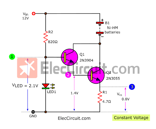
There are 3 points we need to measure voltages.
- Measure voltage across LED1 should read about 2.1V. It will keep the circuit running and stable.
- Point 2 is about 1.4V, results from Q1 and Q2 conducts.
- The voltage of R1 needs to be about 0.8V, Output current will be constant to the battery (load).
We tried charging one AA Ni-MH battery. See the Figure below.
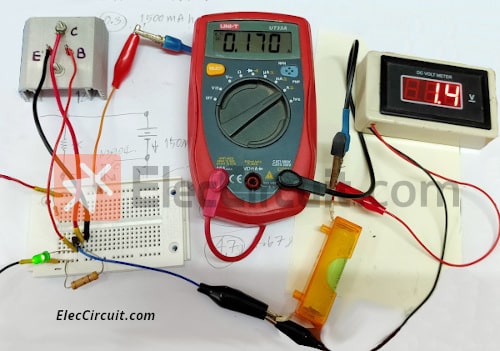
Then, measure the current is about 0.170A. Meanwhile while charging, we measure the voltage drop across The battery as 1.4V. No more than the specified value is 1.5V. Then, we tried charging it for 16 hours. The battery is normal, not more than 40 degrees Celsius.
Note: As the circuit operates, Q2 rises in temperature. Therefore should be installed on the heatsink. and if charging only one battery we may try to reduce Vin to 5V. The Q2 has a lower temperature. Sure, Vin should be regulated power supply.
Thanks, Harald Brötell our friend who sparked trying this circuit. We had a lot of fun.
I and my kids love to learn electronics. I also found a Simple Constant Current Generator using Transistor with helping of TL431, Even though it uses IC. But it is good learning more.
In conclusion, We hope this circuit will be helpful to you. If you have tried What results did you get? Please don’t delay, share with us
Here are three circuits similar to the circuit above:
- LM317 constant current
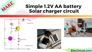
- Simple 1.2V AA Ni-MH Battery Solar Charger circuits
- Experiment increase current of 7805 with 2N3055 transistors
Download This Post
All full-size images and PDFs of this post are in this Ebook below. Please support me. 🙂
Related Posts

I love electronics. I have been learning about them through creating simple electronic circuits or small projects. And now I am also having my children do the same. Nevertheless, I hope you found the experiences we shared on this site useful and fulfilling.


This is a very good tutorial, thanks for it.
Hi Kovács Attila,
Thanks for your feedback. We’re so happy. It is helpful for you
Have a good day,
Yes, very good tutorial..Thanks too!
Took courses long ago, starting to get back into it! would you have a manual with basic projects in it to start.
It’s a good sound. Electronic learning experiments can be fun. We spend a lot of time worthwhile. Time passed really quickly. I’m not sure you mean the academic manual, right?
Hello Robert Elliott,
I don’t have any academic manuals. When I was in school, I was rather lazy to study academically. I prefer to experiment with creating projects to solve problems.
Of course, we use academic principles in every circuit, it’s challenging to understand or calculate its value.
In short, I don’t have any high academic manuals, I only have manuals on projects or related calculations at a basic level.
Thanks
Apichet
The circuit is really a MAXIMUM CURRENT circuit. At 0v, the current is zero. As the voltage increases to 1v, nothing happens because the LED needs about 2v to start to illuminate. At 1.4v the voltage on the base of the transistor cannot rise any further due to the 2 diodes. But nothing else happens. At 2v, the LED starts to illuminate because the transistor has already been turned ON when the voltage is 1.4v.
As the voltage rises over 2v, the LED starts to get brighter and the transistor is fully turned ON. Increasing the voltage allows the LED to pass a higher current and when the current through the emitter resistor produces a voltage across the resistor of exactly 0.6v, the transistor will see a voltage of 0.6v between its base and emitter leads. At this point the transistor is still fully-turned-ON and the LED is as bright as it will ever be.
If we increase the voltage, the LED would normally get brighter but this circuit stops the LED getting brighter.
What happens, is increasing voltage allows the LED to pass a higher current and this current puts a higher voltage across the emitter resistor and this higher voltage decreases the voltage between the base-emitter leads of the transistor and makes the transistor turn off a small amount.
When the transistor turns OFF slightly, the voltage between the collector and emitter leads increases, so that the increase in supply voltage appears across the transistor terminals and the current through the LED and emitter resistor only increases a very very small amount.
You can increase the supply to 12v or even higher and the transistor will get turned OFF more and more and the excess voltage will appear across the collector-emitter terminals. It will turn OFF more and more because the current through the emitter resistor will increase a very very small amount to make the transistor do this.
I appreciate you, Mr. Colin Mitchell, taking the time to inform us of helpful additional details. I respect your experience; you are one of the world’s most significant electronic figures. And you are a great role model for us. Thank you very much.
Nice tutorial…
But, I am a bit confused, when you state the following:
From principle: IE = IC x IB,
As far as I remember from school, IE = IC + IB….
Thanks
Hi,
You are correct. We just improved it.
Thank you for your opinion. 🙂