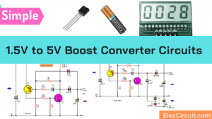
This circuit is a boost converter which is different from the buck converter circuit we have learned about before. That is this circuit increases the voltage from USB 5V to 12V DC to DC by a step-up converter circuit.
This is an experiment about using a transistor as a switching supply instead of IC, which has been popular in this usage at the current date. Because it has high efficiency than the transistor.
Why bother using it? Because it is a great way to learn the basics of the transistor and other basic components. We currently have these components on hand as well.
Let’s learn about the basics of a boost converter.
Basic DC boost converter
What is a boost converter? In simple, it is the circuit that increases low input voltage to higher output.
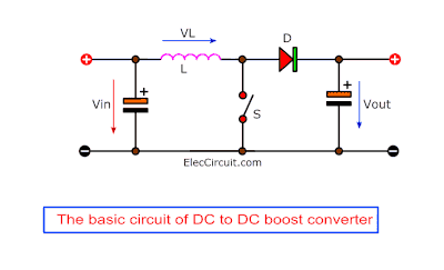
According to the circuit above, a structure is similar to the buck converter circuit. But when we want to design the output voltage rises. So, we connected the switch to the ground instead.
When the switch (S) is closed-circuit causes a voltage drop across L causing VL to match an input voltage (Vin).
Thus, creating the current at the coil (L), by the rate of increase of the current is linear.
But when the switch (S) is opened-circuit, the current in the coil (L) still continues to flow. Because there is the current from the input source integrates with the current of the coil.
Causing these two currents to flow together to a diode (D) making the output voltage higher than the input.
While the switch(S) is opened, there is the collapse of the electric field. Makes voltage inside coil (L) turns to the opposite polarity from a positive to negative.
This resulted in the voltage between the input and the coil’s voltage having the same phase(in-phase) as if we connect two batteries in series, its positive output to the negative end of a second battery, their voltages add up.
Do you see the image?
How DC to DC boost converter works
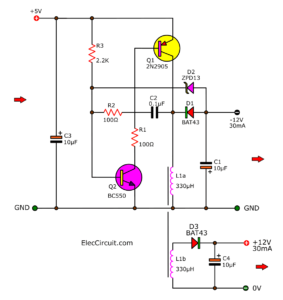
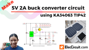
See a complete circuit diagram below. We place the main parts are D1 and L1, they act as a voltage converter circuit.
For the switch (S), we use two transistors Q1 and Q2, they will work feedback to each other.
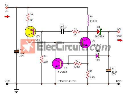
The basic circuit of the DC to DC boost converter
When we enter the input voltage to the circuit, the Q3 transistor starts to conduct a current to the system. Because it is the only one with a full bias current.
The 5-volt flows through R4 to pin emitter to base, through R3 to full cycle with the potential negative of the input voltage.
The results of the transistor Q3 have a bias current, causing its conduction. So, it can provide a higher current from the emitter out to the collector, to send directly a bias current to the base of transistor Q1.
So, makes Q1 into a conduction state as well.
Q1 so is the switch (S) as you see in the first basic block circuit above. Making Q1 conduct (being like S is closed) while L1 is connected to ground (or potential negative).
As the result, the voltage drop across L1 is equal to the power supply voltage of +5 volts, it is connected to the positive voltage and the bottom terminal is the negative voltage.
When Q1 conducts the current, and causes the linear current with coil L1. This current that flows through the L1 is the same as the collector current or the emitter current of Q1.
If the L1’s current rises, the voltage across R1 about of 0.8 volts to 1.2 volts. It makes the transistor Q2 conduct, to pull the current bias of Q1 off, is like the switch that the opened circuit.
So, L1 is cut out of the ground, its magnetic field collapses, there is a different potential. Since L1 is connected to the input voltage that is negative and is added with the 5V in series and in phase.
That is, the output voltage rises approximately: Vout = Vin+V
This voltage is combined through the D1 (Schottky barrier Diode) to supply the output, which there is a C1 capacitor of 10uF to filter a smoothing power.
The output voltage is more or less dependent on the period of storing energy. If a long period, high voltage, because there is strong energy.
But if the low frequency, this circuit also does not supply the higher power up.
Since we need regard to the resonance of the system too. If the frequency is too lower than the resonance, it will not work as the switching circuit.
However, this circuit is a switching regulator circuit, that controls the output voltage of 12 volts.
Because we add the ZD1-Zener diode to keep the stable voltage at 12 volts.
When the output voltage rises up to 12V, causing the ZD1 Zener diode conducts a current to return to the base of Q2. So, the working of Q2 is dependent on changing this feedback output voltage.
Eventually, this can turn off the Q1 transistor, its period of working is shorter, and be able to control a constant voltage of the output.
Testing and Application
We tested this circuit on a perforated PCB. Apply Vin from a USB port, 5V 1A. Then, connect a load is a 12V LED. It glows brightly. It worked!
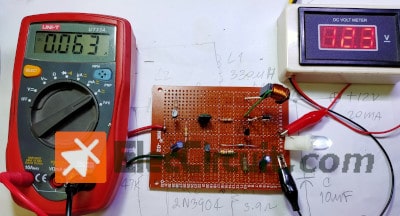
This circuit provides the output current of 20 mA and the maximum voltage of 12.6 volts while the input of 5 volts at the current of 64 mA which is effective in the range of 77% is not so bad.
The components list
- Q1 2N2222, NPN transistor 0.8A 40V
- Q2: 2N3904, NPN transistor 0.2A 40V
- Q3: 2N3906, 0.2A 40V, PNP transistor
- C1, C3: 10μF 25V, Electrolytic capacitor
- C2: 0.1μF 50V, ceramic or Mylar capacitor
- R1: 3.9Ω 0.25W resistor
- R2: 470Ω 0.25W resistor
- R3: 47K 0.25W resistor
- R4,R5: 1K 0.25W resistors
- D1: 1N5819, 40V 1A Low drop power Schottky rectifier
- D2: 12V 0.5W Zener diode
- L1: 330μH, low current rate inductor or Create an inductor yourself
- Perforated PCB, Wires, and other parts
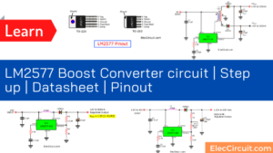
Also, 5V to 12V DC converter using MC34063
Download This Post
All full-size images and PDFs of this post are in this Ebook below. Please support me. 🙂
GET UPDATE VIA EMAIL
I always try to make Electronics Learning Easy.
Related Posts

I love electronics. I have been learning about them through creating simple electronic circuits or small projects. And now I am also having my children do the same. Nevertheless, I hope you found the experiences we shared on this site useful and fulfilling.
Hi my name is Andri.
I want to ask about this circuit, can i use q1, 2, 3 (transistors) with different types of transistor?
Thanks
Warm regards
Andri
Hi,
I am sorry, we cannot use other type of transistor. The Q1, Q2 is NPN type but Q3 is PNP type. You may use Q1 is BD139 because it is high current than 2N2222.
Thanks,
hello
Q2: 2N3904, NPN transistor 0.2A 40V
Q3: 2N3906, 0.2A 40V, PNP transistor
0.2A
I’ve built this circuit twice and I only get 6.68 Volts out of it. I’ve checked the transistors and all seem to be good. I’m kind of at a loss of what to try next.
Hello,
I am happy that you try this circuit. It is small and easy. But It can drive 12V 0.02A load only. If you can read 6.68V output. I think that the oscillator worked if no load we will read about 12V output. Please check the ZD1 it controls 12V output and check C2 and R5 again Sometimes if the frequency is not high it causes low output voltage. Sometimes we need to check Q1 if it has low gain it makes low output volt as well.
Thanks for getting back to me. I am testing without a load when getting 6.8V. I’m getting around 47Khz for the oscillator, but the Q3 collector/Q1 base/Q2 collector is staying at 0V and I’m not getting a switching action. The emitter of Q3 seems to be going to 0 volts the same time the base gets pulled down so it never saturates. What is the target frequency of the oscillator? I may try some different values of the L and C and see how it behaves at different Freq.
I am very sorry for wasting your time.
I checked the frequency at the Collector of Q1 to be approximately 80kHz to 420KHz.
From what I tested, this circuit works normally, but it supplies little current.
The voltage at many points compare with the GND
The C of Q2 is 0.6V
The C of Q1 is 5V.
The B of Q3 is 4.8V
The E of Q3 is 2.6V
Yes. I tested L1 is 68uH to 330uH, All is output to 12V without load. But if L1 is used at a low value, around 68uH, the frequency will be higher and Q1 will run faster. There is a higher current coming out.
However, this circuit was fun, with a few components.
God bless you.
However, this circuit was fun, with a few components.