Will it be possible to create electronic circuits from e-waste? It is possible! We all found that there is more and more electronic waste around us. My kids and I believe recycling electronic circuit boards is one of the good ways to manage them. Let’s build a 5V regulator circuit for the digital experiment.
We have received donations of electronic circuit boards from friends for quite some time. But getting it to work again requires more process than using new components, such as cleaning the PCB (carefully), removing the parts, and measuring it before putting it into practice.
We are delighted and have greatly respected John A Kostelac Jr, and those who have worked for the benefit of Recycling electronic circuit boards to teach children and students in the community after school. In addition to children gaining scientific knowledge. It is also cultivating them to know how to protect the environment as well.
Caution
Before using these circuit boards, we should be careful about The chemicals contained within some devices, such as large electrolytic capacitors, light bulbs, or old TV screens. They may be damaged or otherwise dismantled. There should always be a parent nearby to give advice.
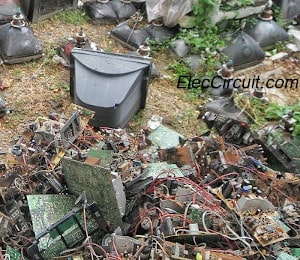
We only take this e-waste to some extent.
But if you want to know more, you can read it at: https://en.wikipedia.org/wiki/Electronic_waste
Attention Recycling electronic circuit boards
Since these devices have already been used before. Therefore, it may have a shorter lifespan than any newer devices. It is suitable for learning or non-essential circuits, and there should be a way to back it up in case of malfunctioning.
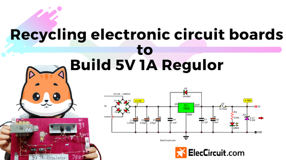
Today I would like to give an example of creating a 5V 1A regulator circuit out of parts from recycling electronic circuit boards (electronic wastes).
I plan to teach my daughter about digital circuits. So, we need a 5V Fixed voltage power supply to experiment with the TTL Digital Logic circuit.
Previously, I thought of using a Wall Adapter Power Supply 5V DC 1A because it was cheap. But when testing with the tester screwdriver, there is an electric leakage at the output. Thus, not safe. We think a safer way is to build it ourselves in a linear-type power supply.
How much power do these digital circuits need?
They require a stable 5V voltage. Because digital circuits will work best at 4.75V to 5.25V. Sometimes they may use a current total of more than 300mA but less than 800mA.
Simple Voltage Protector
The Digital circuit is more important than a power supply
It may be damaged or malfunction if the voltage exceeds 5V. We must protect it.
There are several ways to deal with this problem, such as using a 5V overvoltage detection circuit that will cut off the power supply from the digital circuit immediately when the voltage exceeds 5V.
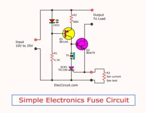
But it’s still too difficult to teach my daughter (In the beginning). I choose the easiest method of using Zener Diode and Fuse instead.
Fuse – sacrifice for others
Do you know the function of a fuse? It will self-destruct (blow) when the current flows through it is higher than its determined value.
For example, if we use a 1A fuse and when the current is higher than 1A, like 1.5A. The metal conductors inside the fuse will become very hot until melting and finally disconnect. So, the current can no longer flow through it.
Fuses are cheap protection devices that do their job well.
Zener Diode – Voltages weir
Basically, while in reverse bias, when the voltage level exceeds the Zener Diode Voltage (VZ). It will let an electric current flow through it and prevent the voltage drop across itself from rising higher than VZ.
Now let’s put these two components into use to protect our digital circuit.
The principle
Normal state
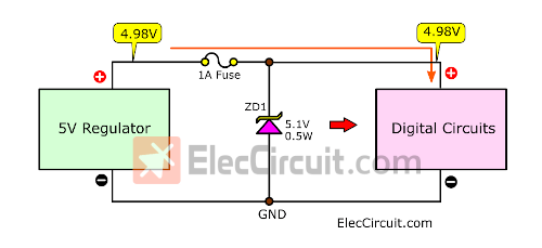
If the input voltage is 4.95V, which is lower than VZ (5.1V), there will be no current flow through the Zener Diode. This 4.95V voltage will then flow to the digital circuit normally.
Overvoltage
On the other hand, if our 5V regulator circuit malfunctions. It gives out voltage higher than normal. For example, if the input voltage level is 5.9V.
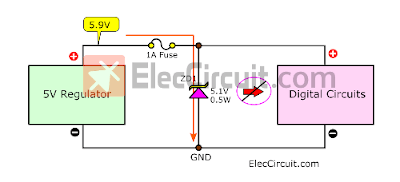
This exceeds the VZ level, so the current flows through the Zener Diode is greatly increased until the current exceeds 1A, then the fuse will blow up immediately. If we use a Fast Acting Fuse, it will happen within 0.5S. Thus, our digital circuit is safe.
Importantly, we should only use new and high-quality fuses and Zener diodes.
Fuse: 1A Fast Acting fuse or fast blow fuse only.
Zener diode: 5.1V 0.5 watts or 1 watts.
Finding the un-dead recycled electronic components
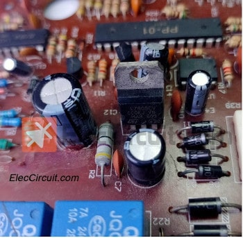
We rummaged through most of the circuit boards we have kept. We found the 7805 inside a 5V Regulator. They were used because of their efficiency, ease to use, and cheapness. So, we will dismantle it for our uses this time.
My daughter decided to remove it from this particular circuit board. We need to unbind the solder joint at the pin of the 7805.
She uses the solder wick or desoldering braid, which is made of braids of copper thread. It should absorb the melting solder liquid just as a dry cloth absorbs water.
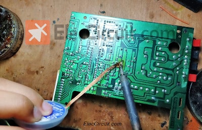
How to desoldering
- Place the solder wick on the solder joint to we want to desolder.
- Place the tip of the heated soldering iron on the solder wick.
- Then we will see the solder start melting and absorb onto the desoldering braid. It is quite hot, so be careful!
- Lift the tip of the soldering iron and the braid from the circuit board.
- The solder joint should be lead-free.
Note: this page has few affiliate links. It does not cost you more. Thanks for your support. I use this commission fee I receive to teach my daughter new projects.
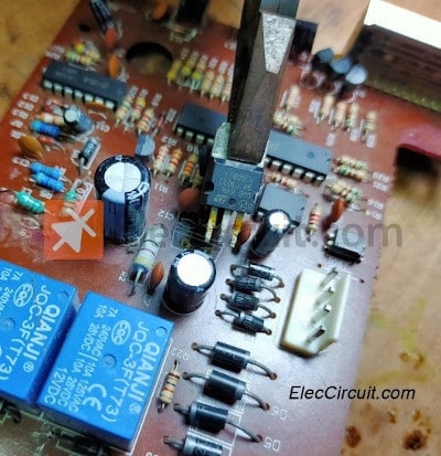
And finally, carefully pull out the 7805 with pliers.
Measuring recycled components
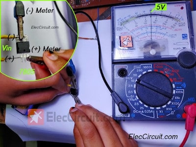
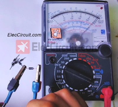
In this step, we use an analog multimeter because they can notice the change in value faster than a digital meter. It is suitable for general uses. But the disadvantage is the low accuracy and quite tricky to use.
My daughter asked How old is this meter? I replied that it was older than her (my daughter). It is very durable though.
We start by setting the meter DCV range to 10V. Then bring the positive probe to the positive pin of 7805. And the negative probe to the metal body of the IC (negative pin). Next, apply a 9V battery as a Vin. If the IC is still working. The multimeter will read out a 5V voltage level as shown in the illustration.
Do you interest in this multimeter? Check it out. (affiliate link)
We know that the 7805 regulator IC starts to work at 7.5V DC input voltage. And in my experience, the appropriate voltage level is about 9V to 10V.
But in some scenarios we cannot find a voltage at that level, the closest one is 12V from an unregulated power supply circuit.
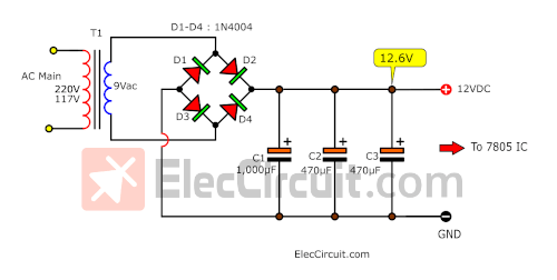
Since the AC voltage level straight from our transformer is 9 VAC. When converted to DCV it is approximately 12 VDC (9VAC x 1.4 = 12.6VDC)
The next step is to search for other components for this 12V 1A unregulated power supply circuit.
First, we take a 1A 9V transformer from an old amplifier circuit. We check it with the multimeter and it is alive!
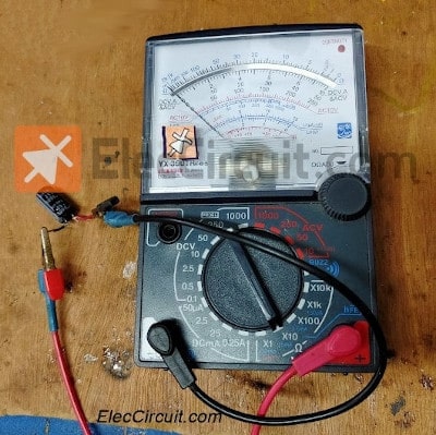
Secondly, we use four 1N4004 diode rectifiers. My daughter removes them from one of the circuit boards. She tested them with the multimeter on a Ω RX1 range.
When measured on one side the dial will sit still, but when swapped to another side the dial should be at the full gauge, indicating that the diode is normal.
Thirdly, we use 1000uF 25V, 470uF 50V, and 470uF 25V electrolytic capacitors as filters. When connected in parallel, it will result in capacitance of almost 2000uF but only can withstand voltage equal to the smallest capacitor in the chain, 25V. Then, we put this method to work. It does work well because of the full output current of 1A.
Testing whether electrolytic capacitors are usable or not with an analog multimeter is very simple.
First, it must be completely discharged by touching two of the leads together.
Then set the multimeter to the Ω Rx10 range and connect the probes to each of the capacitor’s leads.
We will notice that the meter dial is tilted to the maximum. (lowest resistance value) and then gradually decreases to the minimum (highest resistance value). When swapped to another side, it will be like this again. This shows that the capacitor is normal.
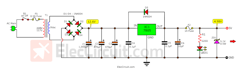
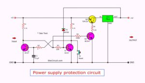
After choosing our main components, let’s take a look at the full circuit of this project, as shown in the figure below.
This list sums up the rest of the devices.
- C4 and C5 reduce noise, or spike voltage should be placed as close to 7805 as possible.
- C6 increases the efficiency of the IC at high current loads.
- D5 prevents negative voltage from flowing back into the circuit, also known as reverse-bias protection.
- LED1 indicates that the circuit works properly by outputting a 5V voltage.
How to Recycling electronic circuit boards
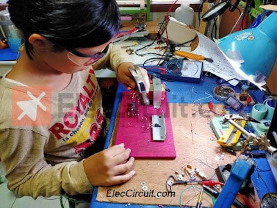
Once we know the details of the circuit and have all the components we need, the next step is to start to assemble it together. My daughter does not want to use a regular PCB. Because she noticed that there were quite a lot of wooden boards and wanted to try making electronic circuits with a hammer and nails like her brother.
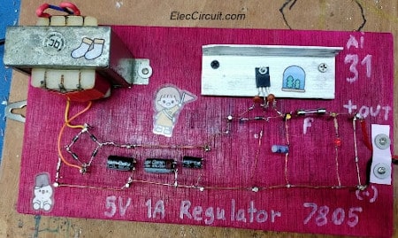
So, we take the old wooden board, about 27 cm x 15 cm x 1 cm, to polish it with sandpaper and spray paint for beauty.
Then install various components, especially the transformer, which needs to be mounted with screws. And cover the AC main connection part properly.
For other components, we use the method of pulling copper wire with nails and then soldering the joint together according to the circuit above.
The leads of all components is too short. Therefore, it must be extended with copper wire.
We almost forgot: there should be a suitable heatsink installed on the 7805 IC.
My daughter likes this method because she says that it is a work of art.
The prototype circuit she has completed.
The components list
- IC1: L7805 or LM7805 or KIA7805, 5V Regulator IC
- D1-D5: 1N4004 or 1N4007 Diodes
- C1: 1000μF 25V Electrolytic Capacitors
- C1: 470μF 50V Electrolytic Capacitors
- C1: 470μF 25V Electrolytic Capacitors
- C6: 10μF 50V Electrolytic Capacitors
- C4, C5: 0.1μF 50V Ceramic Capacitors
- R1: 220Ω 0.25W Resistor
- LED1: 3mm LED
- ZD1: 5.1V 0.5W Zener Diode
- T1: 9V 1A transformer
Read also: Electronic Components list
Conclusion
We could be recycling electronic circuit boards. Although the process is quite tricky and there are some limitations. But we believe in every step we always learn something. In particular, the inspection of the components. In the next opportunity, we will recycle electronic circuit boards again and hope it will be helpful to friends.
Download This
All full-size images and PDFs of this post are in this Ebook below. Please support me. 🙂

GET UPDATE VIA EMAIL
I always try to make Electronics Learning Easy.

I love electronics. I have been learning about them through creating simple electronic circuits or small projects. And now I am also having my children do the same. Nevertheless, I hope you found the experiences we shared on this site useful and fulfilling.


Cool Ideas, I’m going to dig through the old circuits Let’s make some experimental plywood boards like this. Merci
Good 👍
Good idea. It helps for Minimize wastage of resources and green world.