This is a 12V 5A linear power supply circuit. Also, how to find resistors onside. I like to use a series of 78xx regulator ICs. Because it is so easy with a few parts.
If we want 12V output. So, use 7812. But Maximum current at the output does not exceed 1A.
What can we do?
Basic 12V positive regulator using 7812
First, look at work only one alone. A circuit is a basic using 7812. It is so easy. When Vin comes into IC-7812. It will keep the fixed output voltage, 12V.
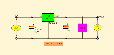
Then, I look at a datasheet Input voltage is 15V to 25V.
In my experiment, I use the lowest voltage level. It causes a low output current. But if using high voltage. It causes the output current to rise. But It is too hot.
So, I choose a medium voltage level is 20V.
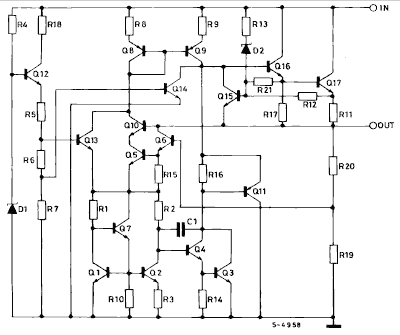
Inside IC has many components. In general use, We do not need to understand those devices. We just use it by understanding its features and limitations.
Capacitor filter
Look at the circuit again. How do both capacitors work?
Cin (input capacitor) — It is between the input pin and the ground pin of IC. We need to use it when the distance between input and IC exceeds 5 cm.
Why?
It will temporarily store power from the input. The IC is able to pull energy to use immediately.
But…
Inputs and IC are close together. It is not necessary to use it. Because IC can get the energy immediately.
If necessary use it. we should choose sizes 0.33μF to 1μF. Most importantly choose a capacitor type that responds to high frequencies as well
Cout (output capacitor)—It improves transient response. Which does not affect the stability of the circuit
12V 1A power supply using 7812
Meet a nice 12V regulator. It is suitable for a mini-load that uses a current of less than 0.8A. You can build it easily on a small PCB layout.
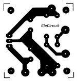
The PCB copper layout on 1.290 x 1.367 on real size printer.
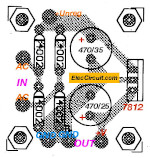
The Components layout of 7812 regulators 12V
Keep reading: Small 5V regulator
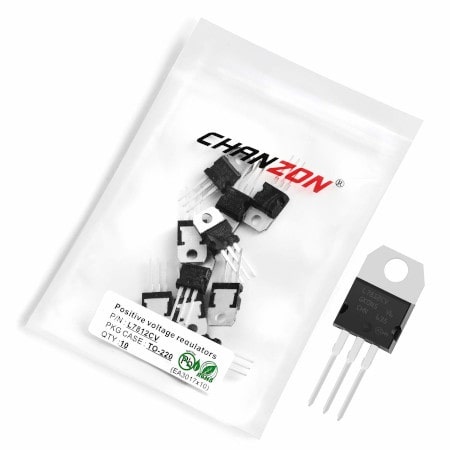
Thanks: Photo L7812 Buy now
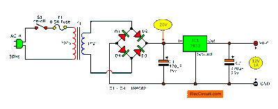
5A Boost Current
Above we need a 5A linear power supply. There are many ways to do it. Let me tell you this way. Using a transistor current booster is suitable. Because it is cheap and easy to build with normal components in a lot of local stores.
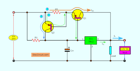
Look at the circuit, many components have a different functions as follows.
- First, both transistors Q1 and Q2 act as increase current up to 5A.
- Second, fuse resistors RS will protect the saturation of transistors Q1 and Q2.
If fuse resistors blow or have high resistances. Causing both transistors to not work.
The current that goes out to the load will have only the current of the IC regulator alone.
- Third, resistor R1 sets a bias current to IC-7812. And set the output current of Q1 does not exceed its saturation current, too.
Then, meet the current.
Still, look at the circuit again.
The output current is a total Current Source, IT. Which it gets from mixing between IIC and IQ1.
- IIC is the output current of IC-7812.
- IQ1 is the output current of power transistor Q1.
Look back on the path of electricity.
- IIC gets the current from Vin through R1 into pin 1 to Pin 3 of 7812. IC1 keeps a fixed regulated voltage, 12V.
- IQ1 comes from working together of both transistors Q1 and Q2.
See 3 steps in the current flows.
- First, a base current of Q2 flows to its emitter. And, out of a base of Q1 through pin 1 of 7812 to ground as compete for a circuit.
The base bias current of Q2 also causes the base current of Q1 can flow.
So, resistance and voltage across emitter and collector of both Q1 and Q2 are low.
- Second, there is a collector of both transistors. Because…
The output current of Q2 flows from Vin through an emitter to the collector. Via pin 1 of 7812 to complete the cycle circuit to the ground.
- Third, the output current of Q1 flows from Vin through a fuse resistor RS. With the working of Q1, the current flow through pin 3 of IC1 to power the load.
How to design 5A linear supply
We have details on the design of the components as shown above as follows.
Choosing transistors
1. Q1 Power PNP transistor on shape TO-3, should choose…
MJ29555—ICmax = 15A, CEvoltage = 60V, hFE = 20-70
2N3792—ICmax = 10A, CEvoltage = 80V, hFE = 50 min
BDX18—ICmax = 15A, CEvoltage = 60V, hFE = 60 min
2. Q2-PNP transistor on shape TO-66 should choose…
2N6049—ICmax = 10A, CEvoltage = 55V, hFE = 25 min
2N5956–ICmax = 6A, CEvoltage = 40V, hFE = 20 min
BDX78–ICmax = 8A, CEvoltage = 80V, hFE = 30 min
3. The output current is a total Current Source, called IT. Which it gets from mixing between IIC and IQ1.
IT = IIC + IQ1
4. RS- Fuse resistor is a ratio between 0.6V per IC of Q1(IQ1).
RS = 0.6V/IQ1
5. R1 always has resistance to more than 0Ω. But it must not exceed a ratio between (VbeQ1) 0.6V per bias current of 7812(IbiasIC1).
0 Ω ≤ R1 ≤ VbeQ1/ IbiasIC1
R1 ≤ VbeQ1/ IbiasIC1
Value on circuit
We know the value on the circuit below.
- Vout = 12V—voltage to load.
- IT = 5A—total output current to load.
- Vin = 20V—input voltage to this circuit
- IbiasIC1 = 12mA —the current to cause IC1 run
Transistor booster circuit design steps
Look at the 12V 5A Linear Power supply circuit diagram.
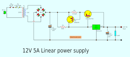
There is component detail as follows.
1. I choose Q1 is 2N3792 and Q2 is 2N6049 respectively. Because they are so easy to buy and cheap.
2. The Q1 must power an output current up to 5A. Also, IQ1 is 5A.
So…
RS = 0.6V / IQ1
= 0.6V / 5A
= 1.2Ω
And the power of RS can find with…
PRS = IQ1² x RS
= 5A x 5A x 0.12Ω
= 3 watts
Thus, I choose resistor is 0.12Ω at 5W.
In normally, a regulator IC-7812 can power current to 1A max. But we set a bias current of 12mA. Or
IbiasIC1 = 12mA = 0.012A
We can find R1 with a formula.
R1 = VbeQ1/IbiasIC1
= 0.6V/0.012A
= 50Ω
Choosing a transformer
My friend ask me “Could you please tell me what the power of the transformers should be?”.
For example.
12V 1A Power supply. How many amperes should I use a transformer?
And, 12V 5A, transformer rate?
Normally, a transformer can supply a little more current than specified, such as
You need a 3A power supply. The minimum size of a transformer that should be used is a transformer of 3A. Because it can supply a minimum of approximately 3A. It may supply a maximum of 4A or 4.5A.
Of course, you may use a 4A transformer. It is good because the current can be power higher. But it will be bigger and more expensive, is it worth it for your work?
Check out these related articles, too:
- How 741 Op-Amp Power supply Circuit works
- Transistor series voltage regulator with overload and short circuit protection
- Power Supply for Audio Amplifier, multiple output 12V, 15V, 35V
Recommended: 12V 10A to 30A liner supply
GET UPDATE VIA EMAIL
I always try to make Electronics Learning Easy.
Related Posts

I love electronics. I have been learning about them through creating simple electronic circuits or small projects. And now I am also having my children do the same. Nevertheless, I hope you found the experiences we shared on this site useful and fulfilling.
Can i change the input voltage for 19v without change anything?
Hi Mohammad Alawneh,
I am glad you are interested in this circuit.
It is good at learning a high power supply.
I want to help you. But I am sure I understand you said clearly.
See in my circuit DCV is 20V. Do you want to use this DCV is 19V.
If yes! You can use it without change anything.
I miss when I was a young who likes to test the power supply circuit. Changing parts and testing. It is also fun. You maybe like me.
Thank you very much
How can I communicate with you?
Your facebook account or anything
Yes i meant this
How i can communicate with you
I have some questions
Thank you very much for thinking about me when you have a problem. I want to help you. But since I have many tasks to do. I conveniently answer questions through this. and email only. I am sorry for slow.
Hello,
Thanks for the circuit and in depth explanation.
It seems so simple, I think I’ll give it a go instead paying premium for commercial linear PS.
One question, if I may.
I want to power a Eurorack synth case, which requires +-12V.
Would I just build 2 of your schematics and connect them as per “+- voltage from two batteries” where the GND comes from the connection of +of one and -of the second battery and +from+, -from- of the two.
Or, do I need to change the design?
Long question, but wanted to explain as much as possible.
cheers
Can you show more the Q1 TO3 & Q2 TO66 transistor names ?
Hi man,
Thanks for your answer.
I’m not sure understand your question. But I want to help you succeed in creating electronic projects.
Please return to read the article again. Have the name or number of the transistor.
https://www.eleccircuit.com/simple-designing-12v-5a-linear-power-supply/#How_to_design_5A_linear_supply
Hi,
Thanks for the circuit explanation. Could you please tell what the power of the transformers should be?
For example. 12V 1A Power supply uses 20V ?A Transformer
12V 5A Power supply uses 20V ?A Transformer
Thanks for responding
Hi Jackson
Please read Here again:
https://www.eleccircuit.com/simple-designing-12v-5a-linear-power-supply/#Choosing_transformer
I’m still trying to understand some of your calculations.
According to the Datasheet for Q1 2N3792 the required Vbe(on) voltage is 1.8V for 5A current flow through the collector.
You calculate RS = 0.6V / IQ1 = 0.6V / 5A = 0.12Ohms (I corrected your formula)
Why are you using 0.6V instead of 1.8V?
Hello JoeScholz,
Thanks for your feedback.
In principle, Voltage BE saturated is about 0.6V, but for this circuit, I have never really tried it.
I’m sorry if you tried it and it works like that.
I believe you can do it. If it works. Please do not forget to come back and share it with me.
Thanks