Here is a high current 13.8v power supply circuit. What for? Those who want to use a car radio transmitter in the house. You should use a 12V/13.8V Ham Radio power supply.
It is a better way if be a High power out of 5A to 30A according to the size of the transmitter.
And I highly recommend this high-current power supply circuit. Because of Good performance, the output voltage of 13V to 14V depending on the load.
Also, you can change/add components to set the output current of 5A, 10A, 15A, 20A, 25A, 30A. According to real usage. So, help to save and easier to build.
Recommended: Learn Basic Electronics
Why this circuit interesting
Of course, you can buy a power supply that simple and effective with a variety of sizes. But if you build them with your own or your friends. It will be a great time while creating this project. And when completed, runs in its function. It will very proud.
Besides, this power supply circuit is also useful as a wide variety. Such as A large DC motor, car audio system, and others. Which you may apply by changing the voltage and current as needed. This circuit is very flexible.
The high current 13.8V power supply circuit
Concept of circuit picking
We want the circuit that uses normal parts. So easy to buy in locals stores near us, and cheaper.
Sometimes you may have these components in your house.
Imagine, you have a lot of power transistors, 2N3055. Because it is popular in the transistor power amplifier.
A linear power supply circuit is a better choice. Because it is so easy circuit.
We often use the three-terminal regulator IC likes 78xx, 7812, or 7815.
Read: 7805 datasheet & Pinout
But It is a big size with large components.
For example, the transformer if you want 30A output current. So you need the least of 30A transformer. It is so big.
By the way.
Its size is not a problem for you. Suppose that you get a big transformer from your grandfather.
Yes, you can try it.
I love the linear circuit.
Note: If you are beginner this circuit may is not suitable for you. You may use circuits below.
- Variable DC Power Supply —First projects.
- 12V 2A AC adapter—It is easy to do with a hammer
- Learn more: Designing 12V 5A Linear Supply
How high current 13.8V power supply circuit works
It must have quality Checklists!
We need these.
- Good protection circuit—When the output short circuit or overload.
- You can also choose to build a circuit size with output currents as you need. You can increase the current in a step by step, each step of 5A. Start with a minimum currents rate of 5A. And next step 10A, 15A, 20A, 25A and a maximum to 30A.
What is more? See parts of circuit.
Unregulated power supply
This circuit requires a high current DC voltage. See in the circuit below is 21V 30A unregulated power supply circuit.
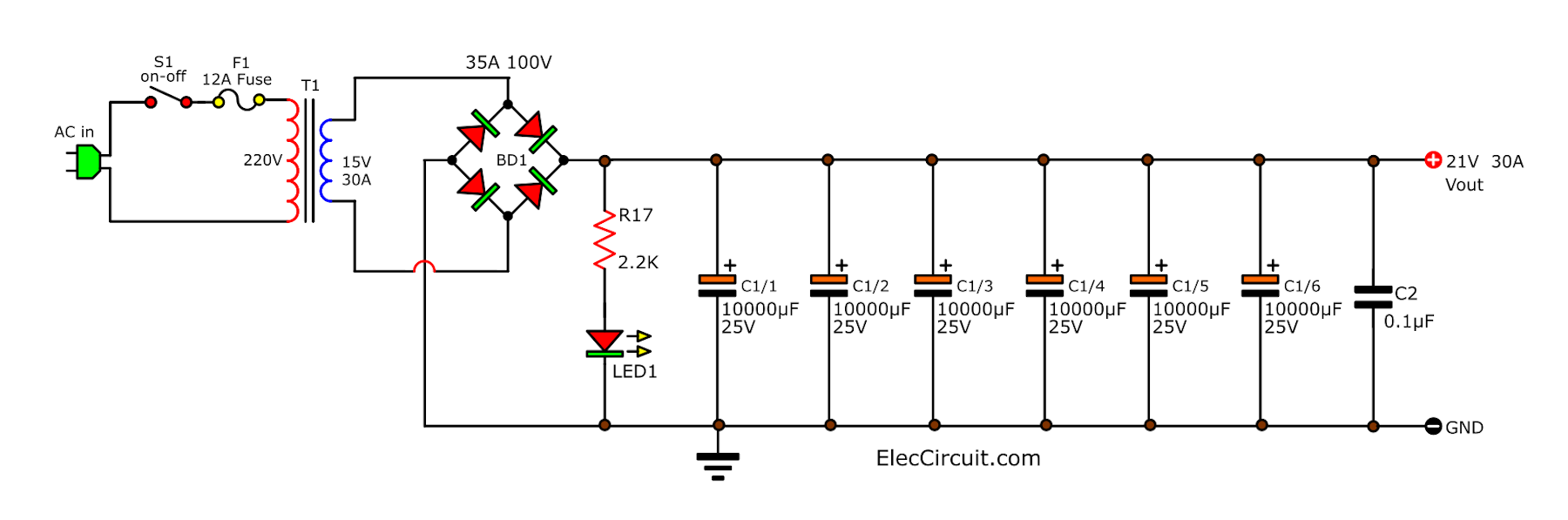
It is flexible. You can choose a variety of devices as you want, follow these steps.
1. The C1 and F1 using this table.
| Output Current | C1 | F1 |
| 5 A | 10,000μF | 2A |
| 10 A | 15,000μF | 4A |
| 15 A | 22,000μF | 6A |
| 20 A | 33,000μF | 8A |
| 25 A | 47,000μF | 10A |
| 30 A | 68,000μF | 12A |
Suppose You want to build 15A output current. With the output voltage of 13.8V.
You should choose C1-22,000 uF 25V.
Equivalent capacitors
But it may do not for sale. We may use five of 4,700uF 25V capacitors to connect together in parallel. So, we have a total capacity of 4,700 μF x 5 is 23,500μF. It is enough to use.
In 30A output, if you cannot buy a 68,000uF 25V electrolytic capacitor. You may use 10,000uF 25V x 6 connect together in parallel. It saves money and easy.
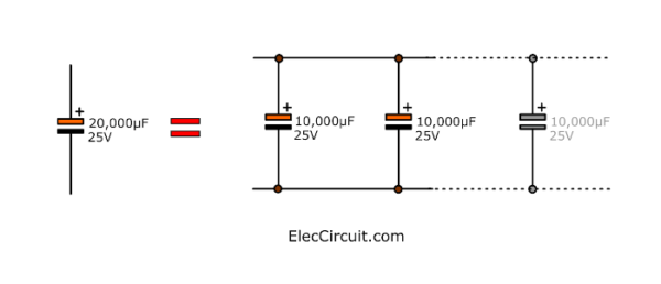
For example you want 20,000uF you can use 2x 10,000uF.
Use the size of 5A fuse is a slow, or Slow blow fuse.
Constant voltage regulator
This 13.8V power supply circuit uses a regulator IC, LM340T-15. It keeps the level of constant voltage of 15V. Inside this IC has short circuit protection and prevents overheating.

As a result, this circuit can keep the level output voltage as well. And, If there are overload or short circuit. It will do not damage too.
Note:
Now We should use LM7815 because it is popular than that one.
How is current higher
In normal 7812 can power only 1A. We need helping from power transistors, 2N3055.
First, see this circuit. It is a Zener diode and transistor regulator that we are familiar with well.
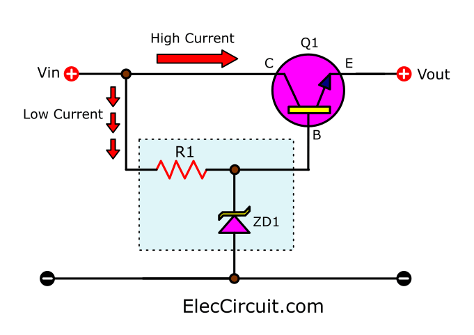
Imagine if we use 7815 instead of the Zener diode.
And use a power transistor to increase the output current more.
Learn: Fixed voltage regulator working principle
You may like to see these too.
- Power Supply for Audio Amplifier , multiple output 12V, 15V, 35V
- 3 Over & under voltage protection circuit for Induction Motor
- 200 watts home power inverter project using SG3526N
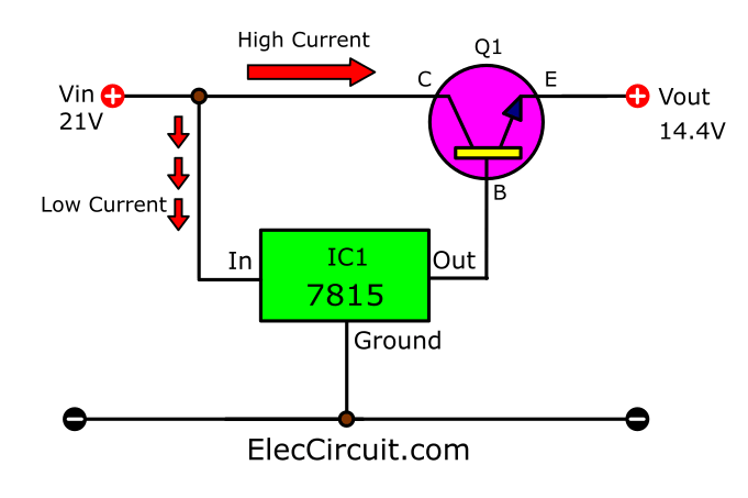
The output voltage is 14.4V. Because 0.6V voltage drop across BE of transistor.
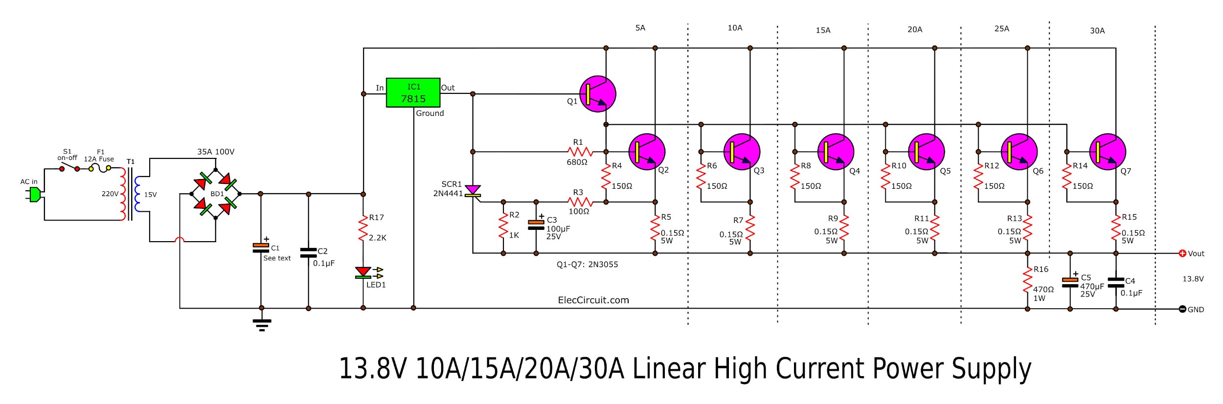
Next look at the full circuit diagram again. At output pin of IC1 will be connected to the Darlington emitter follower with the transistor-Q1. Then, Q1 drives six transistors Q2-Q7 in parallel.
Why connects transistor in parallel
To increase the current up. When to connect these 7 transistors Q1-Q7 to complete. It makes can boost up to 30A.
By parallel with the transistor Q2, from the Q3 onwards. Each transistor can increase the current of 5A.
The resistor 0.15Ω at the emitter of each transistor has two act as are:
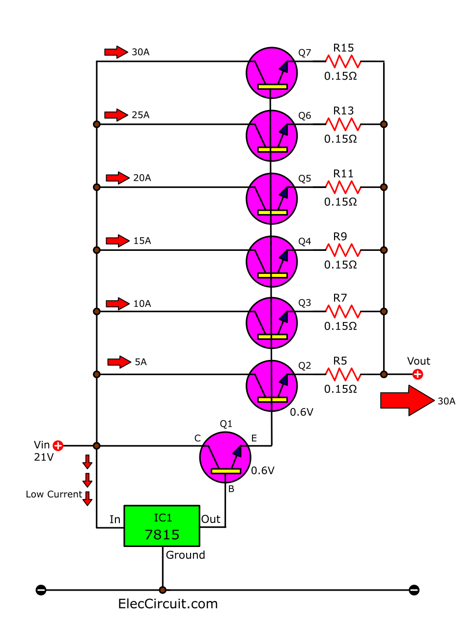
- Check the current flowing through the transistor. Because there is the voltage drop across them as a ratio of the current flowing through each transistor.
- Set the current through the transistor to equally.
Read more: Current limiting resistor
Note: Q1-Q7 is 2N3055 NPN power transistor. Also, you may use TIP35 High-Power Transistors in TO-247. But it is more expensive than a 2N3055.
Better protection
LM340-15 or LM7815 has a wonderful protection system.
- Short circuit or over current,
This power supply is not broken. IC1 can prevent overload very well. Even being a long-short circuit throughout the day. It is still in good condition. - Hot does not work.
When the temperature its highly unusual. The high-temperature protection system will order it to temporarily stops responding. Until the temperature drops. It is started as usual.
With the advantages of this IC. It should be installed on a heat sink near the transistor.
When IC1 has been heating up over defined transistor. It stops! Of course, there is no current to the transistor. So, It gradually reduces heat down. IC1 will return to run again.
Keep Reading: Electronic Circuit symbols
SCR Overcurrent protection
In the short-circuit conditions. Or Overload, Or Using too many currents. The Q2 is pulled by the current of 5A. Until the voltage of 0.75V drop across R5 – 0.15 ohms. (emitter pin of Q2). Then, this voltage to gate lead of SCR1. Next, it is enough to trigger SCR1 works immediately.
IC1 is temporarily stopped responding. Because it is overloaded. By earlier, the current of 1A flow through the IC1 and the SCR1 into loaded directly. Not through all transistors.
The SCR1 is working to hold. Until the power supply is cut off. Which automatically resets itself in this manner is called an Electronic circuit breaker.
How much output voltage
The output voltage of the high current 13.8V power circuit is equal to the voltage output of IC1 (15V) minus the voltage drop across the base (B)- emitter (E) of transistor driver (Q1) and the transistor through (Q2) and the voltage drop across R5 emitter of Q2.
Vout = vIC – vbeQ1 – vbeQ2
= 15V – 0.6V – 0.6V
= 13.8V
However, since the voltage drop across R5 may be changed by the current flowing through it.
So, making the voltage output of this circuit is slightly changed the switch from 14V (under no load) It may be of 13V in fully loaded conditions (regulation).
At this level, it will be maintained voltage is better than on the electric of a car. Its output voltage can be changed from 11V to 16V.
And the transmitter is normally used in the car with 12V battery is designed to be compatible with existing 13-14V voltage.
How it builds
Because the components used in this 13.8V power supply circuit there is not much. And most of them are large. Which must be installed on a heat sink.
The operation of this project, so no need to use a PCB. May use point connect the power cord, tighten the nut onto the heat sink. Then, Connect the wires to the other parts onto the heat sink.
Choose parts as you want
2. Choose a bridge diode rectifier And the transformer T1 according to usage.
Because LM7815 requires a low input voltage to 17V. So, the input DC voltage to unregulated to output drop across C1 should be between 18V to 20V.
If less than 17V may not be enough to use the circuit. And, If more than 20V over 20%.
It may have more energy a loss in transistors and ICs. Making must use a larger heat sink. It is too consumes more energy than necessary.
You may choose the size of the transformer 15A. My friends go to the core steel EI at an antique store, then go hire made a new transformer. This is durable and inexpensive.
Lie detector circuit
Relationship voltage current resistance and Ohms Law
The power transistor—You can use 2N3055 which easier to buy. Or use TIP3055 is the same as 2N3055. But easy to hold on the heat sink with TO-3P. The Best, TIP35 is more high-power current more than 25A of collector current.
You can select any number SCR1 is 200V 5A such as 2N4441, C122, C106, etc.
You can add LED display to show power on by this how.
Note:
If you not like this circuit you can look others circuit more below.
- 0-30V 20A High current adjustable voltage regulator circuit
- Power Supply for Audio Amplifier, multiple output 12V, 15V, 35V
- Boosting the Regulator Currents for IC-78xx
- LM338 | Datasheet | Adjustable Power Supply 5A and 10A
GET UPDATE VIA EMAIL
I always try to make Electronics Learning Easy.
Related Posts

I love electronics. I have been learning about them through creating simple electronic circuits or small projects. And now I am also having my children do the same. Nevertheless, I hope you found the experiences we shared on this site useful and fulfilling.
Saludos cordiales.
Muy importente esta fuente de poder y de gran utilidad en todo circuito.
Quisiera que incluyan circuitos para disparar IGBT.
Gracias
I think there is an error in that diagram! in the 30 A section, the collector and base of Q7 is shorted rendering the whole regulator circuit
as useless seeing that all bases are in parallel…
that wold leave someone wanting to know, who let the smoke out?
Do you have a corrected or updated circuit sir.
Sam, i made the cuircuit 30 amps , and its running, but the regulator id very hot, i used it in my 75 watts yaesu, tou said it has an error, can you elaborate more clearly.
Thank you
Fgboko
Phils.
Hi phils,
Ok but, first of all. I share my changes in circuit like the transistor im using 2sc5200 as driver and 2sc2922 as power transistor and i add irfz44n as my voltage variable to give proper voltage requirement to lm7815.. i will share a pics of my project.later
Tnx.
Fgboko
Dear sam, you are right.
sir,
reg ic 7815 is much over heated when i short the out put supply. kindly let me know what should i do. another thing, in put voltage to ic 7815 is about 24 vdc, is this high voltage is the matter.
thanks and regards.
if one of transistor or LM will bow up or LM will lost it’s ground you’ll get high voltage in output.
Got it twice under developing conditions, I will add overvoltage protection in output side.
If I were to use 2N3055 transistors for Q2 -Q7, would the values for the base and emitter resistors be the same?
please tell me that is this work or not.
Is This Work Or Not?????
Plz Tell Me .
Excellent circuit,really formidable,this is very easy to understanding
Thanks
What diode model you use in the bridge ? bdi 25A 100V , i cant found this diode…?
BD1 I am sure he is referring Bridge Diode number 1 BD1 not bdi which is a full wave bridge rectifier at 25 amps.
Correction with the trace from Q6 base to Q7 collector ommited in the link below.
https://files.qrz.com/q/kd4obq/highcurrentreg.jpg
73
The transistor Q7 base and collector are in short.
To fix that,the wire going truth colector must finish Q6 collector?
Thanks for your attention.
I believe is going to be a very good project.
Thanks again.
Narciso.
For the 30 amp. Circuit where go the 12 amp. Fuse.
Thanks.
Narciso.
As I can see from datasheets, I can use 2n3055 transistors instead TIP3055 without any other changes. Am I right?
Thanks for circuit!
is the above correct or the one given by ECStrat correct????
plz help….
is the above circuit diagram correct or the one given by ECStrat correct????
plz help….
I am in need of a scumadic for a 110V AC, 13.8V 100A DC power supply. I will now tell you what I have and what has been done so far. I have a 3 stage 110V 13.8, 14.6 and 17.5V output transformer capable of 100A. I am using 2N3002 pass transistors X 12! 2 driving 10. I have 2 100V 1000A Stock Astron bridge rectifiers, a 723 complete board, 63V 180000uf cap etc. I am wiring up the pass transistors 2 driving 10 using the crow bar wiring! 0,1 10W ceramic resistors! I already have the pass transistor mounted in 2 6 bay TO2 heat sinks. I am in need of a complete wiring diagram if you could showing me how to wire this thing. You wouldn’t believe how hard its been to find any info on crow bar wiring let alone find someone who can tell me any info on how to wire this thing. I am not new to electronics but this is my first power supply build of this size! Please Help. THX Billy
please tell me which diode used, the rectifier circuit.
Forget this guy. Here’s one that’s similar and actually works. Crowbar and protection explained.
https://sound.westhost.com/project77.htm
First off, the schematic diagram is complete unreadable, appears to have errors and is pretty much worthless circuit. I would suggest finding a more detailed power supply somewhere else.
Dear Sr
i am really happy to ready all over your project. please sr i wont 5vols out voltage and remain all the current.so how
could i do, or i could change ic1 to (7805). thank you .
i have one faulty 24volt /10 amps SMPS.
If i on the powersupply the output LED flickering and the voltages also varying,i want to rectify the SMPS.Kindly give your valuable tips.
thz..
Hello Mom
Nice circuit and works wonderfull. Gutted out an old 1400 watt UPS and the transformer filled the bill perfectly for a 25 amp supply, the parts were cheap and the whole project went without a hitch. Took a little time doing the artwork for the PC board. At 18 amps it drops down to 12.6 volts and at idle with a 1.7 amp load it’s 13.9 colts which is acceptable and will try it with a receiver in the morning and hopefully I will have no chirp on the transmitter. Needed a supply for the bench and it will work perfectly.
Nice design and nothing heats up except the bleeder resistor which I might change out but everything else is cool as a cucumber at a few amps and of corse heats up when loaded.
Thanks for the wisdom
Pat KD4OBQ
AR
pls what value of bridge rectifier can handle up to 30amps?
Se puede utilizar un puente rectificador de 50 Amperios.
is it right that basis Q7 connecting to collector? i thing its not common.imho
I’m looking for a manual or circuit of a Sharp CD-C25x(bk) on pdf or doc please help
Here is the CORRECT SCHEMATIC:
https://files.qrz.com/q/kd4obq/highcurrentreg.jpg
He made one small mistake.
SORRY, I NEED TO KNOW THE SPECIFICATION OF TRANSFORMER YOU HAVE USED (MAX.POWER)
Hello, but you can have the pattern of the PCB. thanks
hi there man i just build this sweet power supply at first i thought it wasnt working so i rechecked and tested every part of the circuit but i figured its because i powered it up when the transformer was already on so the capacitor must of needed to charge and the scr may have tripped took me 6 hrs from scratch to build i got some old power supplies from computers that were blown out and used the heat sinks i bought all the parts it came up to approx 350 TT dollars i would say around 60 us or so i havnt loaded the circuit fully jus yet but i see the potential in it i also used a multitap transformer from a computer grade power supply from the 1980’s and i used tip 35c transistors and a bt151-500r SCR but i used a 150uf capacitor on it i also installed a led light for the output and im gettin a constant no load voltage of 13.52 v boss of a circuit cheers!
dont know the rating of my transformer per say but the output im using read 20.5 v it may be a 30va not sure but it works!
Momename, it would help immensely if you could get someone to proofread and edit your description of this power supply circuit because it is very difficult at times to fully understand exactly what you are trying to describe.
For example: ” – I chose the C1-22,00uF 25V. But not for sale, have to use five 4,700 25V capacitors to parallel these.”
It’s better written thusly: “Because a 22,000uF 25V capacitor was unavailable at the time, I just paralleled five 4,700 25V capacitors instead, which provides the slightly greater capacitance of 23,500uF.”
There’s a really good 13.8 Volt, 30 Amp power supply circuit diagram in the ARRL handbook with clear instructions on how to build it. The voltage is adjustable and it even has remote voltage sensing which automatically compensates for any voltage drop that occurs between the power supply and the load [transceiver]. It uses a very large capacitor of ~500,000uF which allows each of the five 2N3055 pass transistors to run quite cool because they only have about 2-3 Volts maximum dropped across them. If each 2N3055 [or TIP35] pass transistor drops only 3Volts at 6Amps then it will only be dissipating 18Watts [3×6=18] which is quite cool, especially if the pass transistors are mounted on a large heatsink. The main transformer supplies only 12.6Volts AC which when rectified provides ~17.8Volts for the pass transistors and a much smaller transformer provides 15Volts AC for the voltage regulator, which is a LM723 integrated circuit. It also uses an SCR for over-voltage protection and when the SCR is triggered it causes a relay to quickly open instead of blowing a fuse. The relay breaks the circuit faster than a fuse can blow and it’s a lot cheaper too than having to replace a fu$e.
This circuit (not the beaut RF-Proof 30Amp one in the ARRL) would be best wrapped in concrete and sold to someone for a boat anchor.
And the English describing this circuit is lousy.
Hello, I would like to make this circuit but I need variable power supply. Could I add resistor and pot to lm317 and that way change output voltage?
pls dis circuit is not giving me good output current i use 0.22ohm 5wat and bt151 as the scr but am having a droping current of 1amp any help?
Hello sam, but you can have the pattern of the PCB? and can i use 18vdc transfomer on this circuit..? thanks & regards
Please give more details about all Q1,Q2,Q3,Q4,Q5,Q6 & Q7 like volt, power etc and where I can bought all parts from. I m from Raipur chhattishgarh.
I also want to know that how can I blow 2
12 volts 55 watt lamps in my bike discover 100 cc 4g with magnet coil or battery when I connect these with magnet it burns like candle a and when connect with battery it discharge my battery in 15 minutes please tell can I increase its ampiers upto 10 amp or more by little change please give me proper solution ..
Greetings, Friend
You have this already drawn design in Proteus, for I am wanting to set up this project but the biggest problem and draw it if possible if you have the project designed to make the gentiliza send to my email [email protected]
Thank you.
Can I use this circuit to power the car amplifier which require around 25amp constant current…
Sir,
My Question is
If i want to amplify it more than 30A if near 100A so then what should be need to do changes in circuit
Sir I have 220v ac 18watt input can i output about 30amp using this circuit ?
What would be appropriate transformer power for the product? I guess 15V 30W transformer is too small?
If I just need 10 Ampere, R16 C4 C5 I must use it too?
Who ever writes these electronic articles should read the work before posting it because none of these articles make any sense. ????????????????????
dear sir, i have do it, i note that error on schematic ,becouse last tip 35 , the collector is cc with base.
It is OK! Very power, very good,but i’have a problem when i ON. I’think the scr current is very sensible, and a simple car lamp 12v 3A make protection. If i use 1A and following 10A =11A that is OK. The resistor of 100 OHM will upgrade to 120 or 150 OHM???
Thank for your reply.
Best regards…Mike
or R16 < 470 Ohm????
a nice circuit.
thank u
Good circuit. I have built it, worked ok
Buen día tengo un pequeño problema se protege con mucha facilidad y la resistencia de 470 se quema me ayudas ?? Por favor
Want to make dual output 24vdc to 12vdc converter for VHF radio and GPS.
For VHF 13.8vdc, 15A & for GPS 13.8vdc, 10A. Please advice which IC should I use. And other important details.
Can you please suggest equivalent model to c122b. It is no available here in my place.
I used TYN612. And it works. Thanks for the circuit.
Same here C122 is not available..
Can you add a parts list and this schematic is so flue. I can not see any of them
Is there any way possible to simply make this a variable current circuit, for instance changing the current through 5A to 30A
Is the connection above Q7 from its base to the collector, joining the two, a mistake or correct? Thanks
Si conectas 10 condensadores en paralelo de 4.700 microF,obtendras 47.000microF,pero una tension de 2,5v.
Hello Jose Salmin,
First, thanks a lot for visiting my site.
I would like to express my opinion.
Please see this: https://www.eleccircuit.com/uses-of-capacitors-rc-time-constant-coupling/#Parallel_Circuit
I think the capacitor voltage is not going to drop.
I want to hear your opinion. Please advise me again.
Thanks again,
Apichet
In 30amps project i have some changes ang additional cuircuit and when i tested it. it works very fine, im using it now in my vhf yaesu radio.,
Thanks for the ideas
Fgboko
Hi Fgboko,
Oh … it’s very gratifying. Thank you very much for your interest in this circuit. And successfully built it.
Please share with us a picture of your work circuit.
It will be very helpful for others.
Have a great day.
Thanks
Apichet
quais a muidanças que vc fez ?
Can we modify in put voltage up to 40v?
Hello, Maduranda
Thanks for your visit to my site.
I am sorry. In normal IC regulator cannot get voltage more than 40V.
However, we may have other ways to do it. If you have a lot of time, everything possible.
Thanks
Dear Apichet Garaipoom. Can I replace the 7815 with a 7806 and having a 6 volts at the output? I want to use this schematic for driving a number of servo`s. And is the schematic working? Thank you in advance, Marcel.
Hello, Marcel
Thanks for your visit to my site.
I’m glad you’re interested in this circuit. Unfortunately, I am busy. Therefore, I cannot draw a circuit and seriously test it for you.
In the future, I will inform you about this circuit update later.