I often make the small projects. They require the small power supply. But I cannot find the small transformers. The normal transformer is big and heavy, not suitable for my project.
But I look around my home in a small appliance in China. Even, in most LED light bulbs.
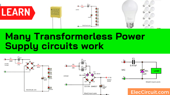
They use the transformerless power supply circuit or use a capacitor instead of a bigger transformer. Thus, power supplies are smaller and lighter.
Today, we will learn these transformerless power supply circuit. So you can select as you want.
Hopefully, it will be useful to you. There are three circuits, as follows.
Recommended: Learn Basic Electronics
SEE Below!
The AC main
First, we need to know the AC MAINS is a high voltage of 220V or 110V. It has a much higher voltage rating than a battery. And also have different signal waveforms.
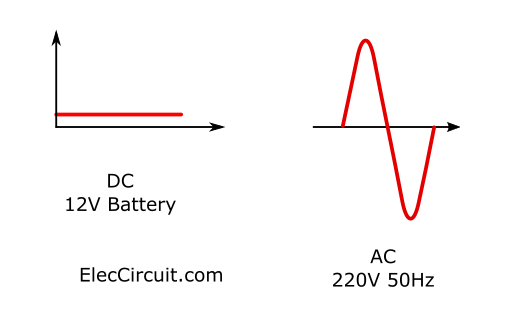
It is called an alternating current (AC). Usually generated by rotating a coil in a magnetic field.
The mains is 50Hz or 60Hz (in USA).
Danger!
Do not touch any part of these circuits. Because you may be hit by electric shocks. Though it makes a low voltage. We cannot touch it all. Because it does not use an isolated transformer.
Why AC Main is dangerous?
Our body can only handle 60V to 80V. So, any overvoltages that can cause instant death.
AC mains Measurement
In normal we know voltage in 0.707 times the peak voltage. It is called the RMS (Root-Mean-Square) voltage. And, the peak voltage (or current) is 1.41 times the RMS value.
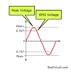
For example, the RMS voltage 220V is 311 Vp-p. It is very high voltage.
The AC MAINS is dangerous. Because the voltage is too high.
It is actually 311v for the 220V AC. or 345V for 240V.
Look at image
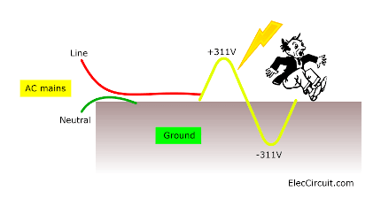
The Line rises 311v then falls 311v below “ground” 50 times per second (50Hz of frequency). Then, this will produce a CURRENT FLOW through your body and it will kill you very quickly.
Basic DC Power supply circuit
Look at below. It is transformer power supply circuit.
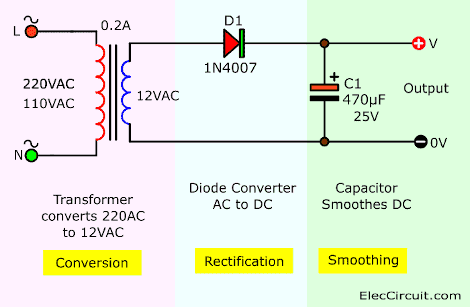
It is basic of unregulated supply circuit,12V 0.2A. Also, we called half rectifier circuit.
We use the transformer to reduce from high AC voltage to lower voltage. See in its symbol. There is the insulation is between the primary and secondary.
And has the two lines indicate a magnetic circuit that exists between the two windings.
Power transformer Separate the coils clearly. We are therefore quite safe for the electric shock. But if using a capacitor instead of a small transformer
CAPACITOR-FED POWER SUPPLY
If the Neutral connected to 0v of the supply. It is no problem.
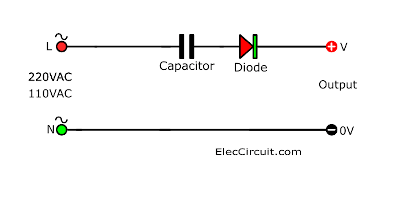
But what happens if the wires are reversed.
The line will connect to the 0V like the hole of the power-outlet on the wall.
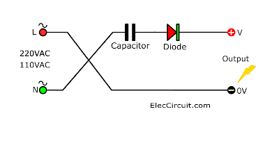
If you touch it. You will get a shock.
Dangers of CAPACITOR-FED POWER SUPPLY
Let’s learn the dangers of a CAPACITOR-FED POWER SUPPLY. And How it works.
What is the output voltage?
In normal circuit with the load connecting, the output voltage
of capacitor-fed power supply only drops to 12V or 35V. is
But…
When the load is removed, the supply rises to 180v or 311V or 340v. That’s another reason why they are so DANGEROUS.
Easy capacitor calculation
All our calculations are made with multiples of 0.1uF capacitors.
This makes the calculations easy.
A 0.1uF capacitor will pass 7mA when connected to a bridge. Or, 3.5mA if only a single diode( half rectifier).
And, all values are halved for 110V AC.
For example. You use 0.33uF. It will pass 7mA x 0.33uF = 23.1mA
Simplest AC mains LED display circuit
Here are the simplest AC mains LED display circuits. Or it is a CAPACITOR-FED power supply that requires a diode and a red LED.
These two items are called the LOAD.
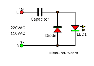
The capacitor passes(charges) current in one direction when the mains is rising. And then, it passes current(discharges) in the opposite direction when the mains is falling.
It is a sine waveform as above.
When the mains is rising and the output of the power supply rises. And when it is 1.7v. The red LED turns ON and this voltage does not rise any more.
So, now the capacitor will store or charge the voltage about 309V. (AC main – VLED).
When the voltage of the mains falls. The output of the power supply will be negative. And when it is 0.7V negative. the diode prevents the voltage from falling.
Then, the capacitor discharges and starts to charge in the opposite direction to 309V.
The red LED is the LOAD in one direction and the diode is the load in the other direction.
Half-wave transformerless power supply
Look at the diagram below. It is the basic half-wave capacitor-fed power supply is shown in the diagram.
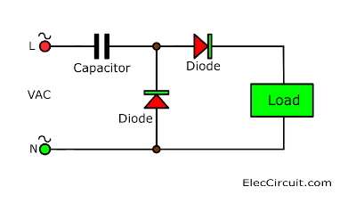
Each 0.1uF of capacitance will deliver 7mA RMS.
In the half-wave supply, the capacitor delivers 3.5mA RMS. Because the current is lost in the lower diode when it discharges the capacitor.
Using a Zener Diode
See the circuit. This is only one Zener diode instead of two diodes, previous. It is a clever design.
Why?
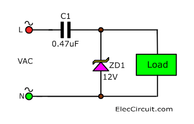
A Zener diode effectively breaks down in both directions.
On the top, It is 12V Zener breaks down on the cathode. And
In the opposite direction, it breaks down at 0.7V.
The load will get a maximum of 12V. And, the Zener will discharge the capacitor. To get ready for the next cycle.
How it works
The output current is 16mA. Because the capacitor is 0.47uF.
When we connect a load. Some current will be pulled from the Zener and will flow through the LOAD.
It has an interesting point.
- Reduce the resistance of the load. Then more current will flow through the load. Until it reaches 16mA. All the current from the capacitor will flow through the load only. No current to the Zenner diode.
- Make the more load until the voltage across it down to 11V, 10V, 9V …. But the current will remain at 16mA. Eventually, the voltage will reduce to 1v at 16mA.
- But if No load, all the current from the capacitor will pass through the Zener Diode.
What is the Rating of the Zener diode?
The Zener diode has a wattage rating like a resistor. This is the amount of heat it will get rid of without getting too hot. If It is overheated. Eventually, it can get damaged. We should pick and set the circuit in rightly.
Often we see 500mW and 1W.
We can find out the wattage dissipation easily.
Its power is V x I
- First, V is the Voltage of the Zener diode. It is 12V.
- Second, I =?
For each 0.1uF, the circuit will deliver 3.5mA
Suppose the capacitor is 0.47uF = 16mA
The wattage dissipation for the Zener diode will be 12×16 = 200mW.
We can use A 500mW. It will not get too hot.
Half-wave cap-fed power supply with electrolytic filter
It like other DC power supply. If we need a low ripple voltage. We need to add electrolytic capacitor filter.
Look:
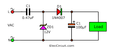
We need to add a diode to prevent the electrolytic discharging in the second-half of the cycle.
We can see that the Half-wave transformerless power supply has the advantage of being simple, but it gives a low current. We should choose a better bridge circuit. Read on.
Using Special capacitor
We must use a special type of capacitor. And it must be rated at 400V AC type. And must be constructed with materials and insulation the not blow up.
These special types of capacitors have the identification X2.
Any capacitor will work. But some will short-circuit or blow-up for no apparent reason.
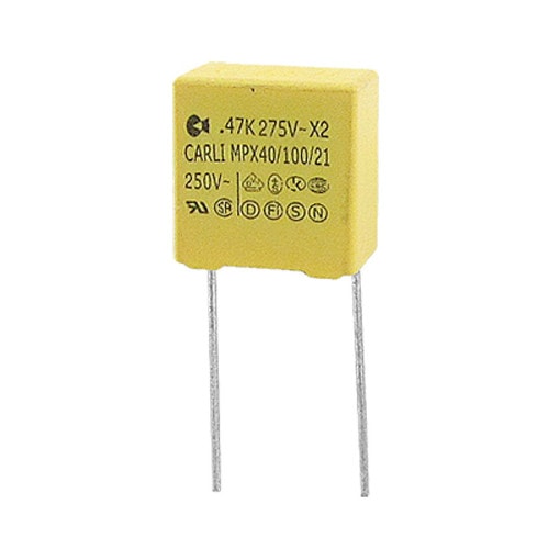
Because the capacitor is charging and discharging 100 or 120 times per second.
There is a certain amount of stress on the foil and insulation. why it must be strongly constructed.
Although there is theoretically no energy lost in the capacitor, it will heat up a small amount due to losses.
The charging and discharging are grouped as ripple current and this current always causes a small amount of heating.
Adding SAFETY RESISTORS
When the circuit is turned ON. We do not know, the mains voltage is zero, a small positive value, or a full 311V.
If it is 311V. In first, a very high current will flow to charge the capacitor. This will damage the LED.
What can we help it?
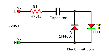
Limit this current. We add a 470 ohms resistor in series with the AC line.
6 LED Display with AC main
See this circuit: 6 LED Display for AC main.
If we can add more LEDs to the circuit. They will ALL glow.
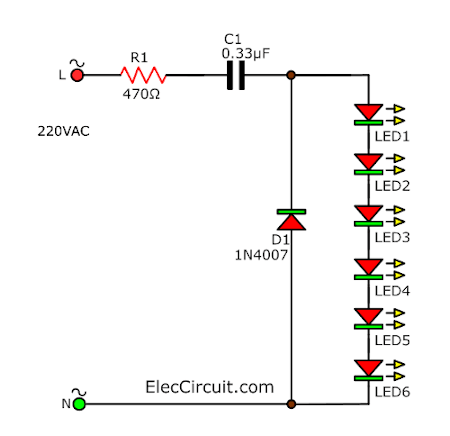
We cannot add hundreds of LEDs. Because as we add another LED, the voltage across the combination increases by 1.7V.
And when the total becomes 311v. NONE of the LEDs will illuminate.
That is because there is zero volt difference between the mains voltage and the LED voltage.
It is not a good design using a single-diode. Because the LEDs are only illuminated for each half-cycle.
LEDs turn ON and OFF very quickly and they will appear to flicker, too. It is a better circuit if use a BRIDGE.
Bridge transformerless power supply
It works like a normal bridge DC power supply circuit. A bridge is a set of 4 diodes. The output waveform is called Pulsating DC or “DC with Ripple”.
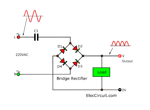
In bridge circuit, we can use lower capacitor. Because it is a full-wave rectifier.
Why?
If using 0.1uF the output current is 7mA. If we use 0.47uF. The output current is? (0.47uF x 7mA) / 0.1uF = 32.9mA
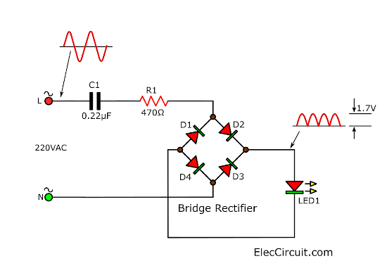
The bridge will deliver 2 pulses of energy during each cycle. And this will result in 100 blinks each second(50Hz).
And if we add more LEDs. They will all illuminate.
Eliminate the flicker
If we want to eliminate the flicker. The output needs an electrolytic capacitor. This will store the energy during a peak and deliver it when the mains voltage is low.
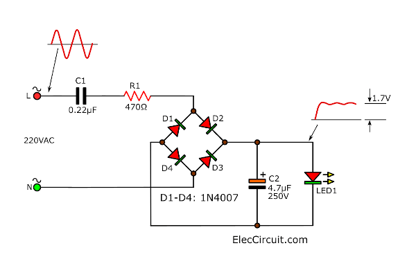
See the waveform on the circuit. The voltage remains high enough to keep the LED constantly light.
100 White LEDs on AC mains
Here is 100 white LEDs Display on AC main. This circuit is easy and very clever. Because No rectifier diodes are needed. We use the LEDs are the rectifiers.
How?
We need to use at least 50 LEDs in each string and the 1K resistor. To prevent them from being damaged via a surge. If the circuit is turned on at the peak of the waveform.
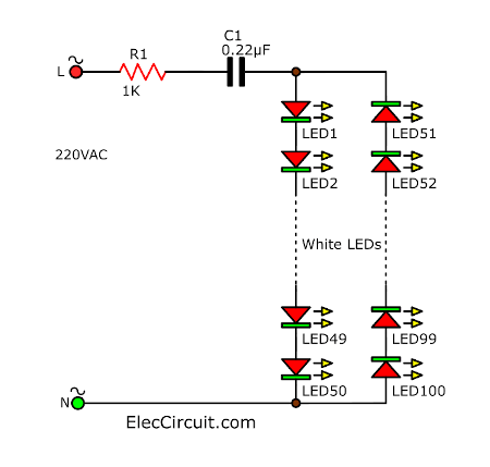
The resistor is provided to take a heavy surge current through one of the strings of LEDs if the circuit is switched on when the mains is at a peak.
Though we can add more LEDs to each string, the current will drop a very small amount until eventually, when you have 90 LEDs in each string, the current will be zero.
For 50 LEDs in each string, the total characteristic voltage will be 180V. Each LED requires 3.3V to 3.6V.
Each LED will take less than 7mA peak during the half-cycle they glow.
Anyway, Look at the 1K resistor. It will drop 7v. Because the RMS current is 7mA (7mA x 1,000 ohms = 7v).
And its Wattage is 7V x 7mA = 49mW
You must have LEDs in both directions to charge and discharge the capacitor.
5 LED Display with best Cap-fed power supply circuit
This circuit is the best cap-fed power supply for 5 LED display.
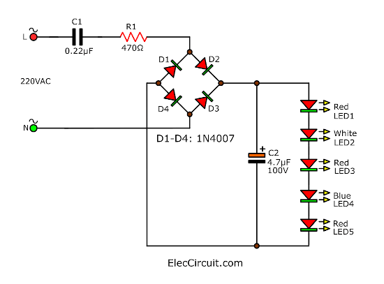
It uses 4 diodes(Bridge diodes) to produce the best current from the 0.22uF capacitor and an electrolytic to smooth out any flickering.
38 LED LAMP using transformerless supply
This is an example of practical use in LED lamps. It is a 38 LED lamp using a capacitor-fed power supply to illuminate 38 white LEDs.
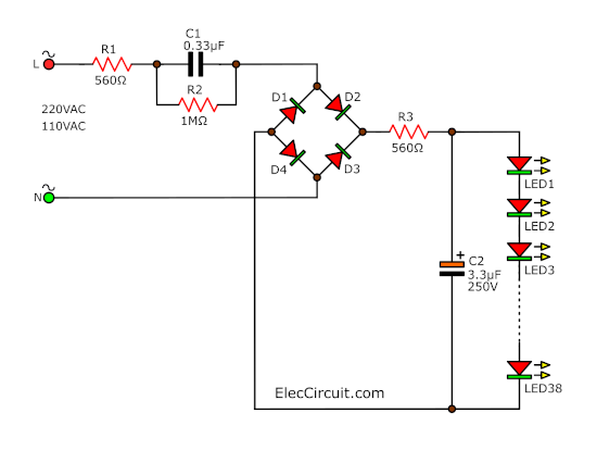
The total voltage across the LEDs is 38 x 3.6 = 138v. The 0.33uF capacitor will deliver about 20mA. At the power about 4.4 watts (220V x 20mA)
Fixed voltage regulated transformerless power supply
Here is a DC voltage regulated transformer power supply circuit.
See in the circuit. This clever design uses 4 diodes in a bridge to produce a fixed voltage power supply capable of the current 35mA.
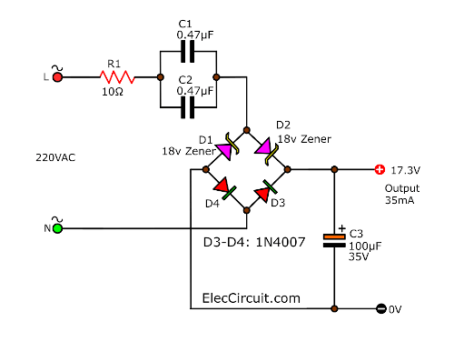
All diodes (every type of diode) are Zener diodes. They all break down at a particular voltage. The fact is, a power diode breaks down at 100v or 400v and its Zener characteristic is not useful.
But if we put 2 Zener diodes in a bridge with two ordinary power diodes, the bridge will break-down at the voltage of the Zener.
This is what we have done. If we use 18v Zeners, the output will be 17v4 regulated power supply.
When the incoming voltage is positive at the top, the D1-left Zener provides an 18v limit. And, the other Zener (D2) produces a drop of 0.6v.
This allows the right Zener to pass current just like a normal diode.
The output is 17v4. The same with the other half-cycle.
The current is set by the value of C1 and C2 capacitors(in parallel). From the Bridge rectifier, the current is 7mA for each 0.1uF. So, we have 1u capacitance. So, the circuit will supply 70mA. but it will only deliver 35mA before the output drops.
The C1 and C2 capacitors should comply with the X1 or X2 class.
The R1 resistor, 10 ohms is a safety-fuse resistor.
The problem with this power supply is this will kill you as the current will flow through the diode and be lethal. if you need to touch the negative rail (or the positive rail) and any earthed device such as a toaster to get killed.
The only solution is enclosed with this circuit in a box with no outputs.
9V DC regulated transformerless Power Supply
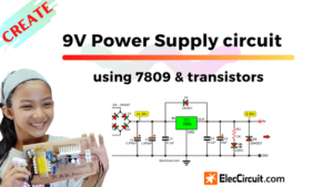
This is 9V DC power supply no transformer, It is an easy circuit and small size.
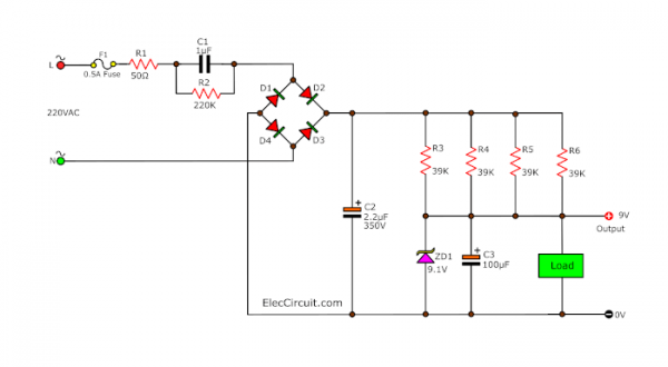
From the principle above. We try to set this circuit.
The output voltage is the same as the voltage drop across the Zener diode-ZD1.
The current can be found 7mA current for 0.1uF capacitor. It should be 70mA. But some current drop R4 through R6 (in parallel). The output is lower 35mA that fixed voltage at 9V. So, we can use this instead of 9V battery.
- See others: 9V regulator circuits using transistor
If you like this circuit look at: AC Siren without transformer
Conclusion
We can see that transformerless power supplies are very useful and popular. Especially in LED bulbs. But I would like to emphasize on safety. Always come first.
Note:
Although I used to use this type of power supply circuit. In appliances made from China.
Many friends are interested in it. So I learned from many places. I found Mr. Colin Mitchell to describe it very easy to understand.
Thanks. Source http://www.talkingelectronics.com/
Read Next: 5V Transformerless supply
GET UPDATE VIA EMAIL
I always try to make Electronics Learning Easy.
Related Posts

I love electronics. I have been learning about them through creating simple electronic circuits or small projects. And now I am also having my children do the same. Nevertheless, I hope you found the experiences we shared on this site useful and fulfilling.
very useful ckts.
require over load protection ckts.. plz help.
These circuits on this page are VERY dangerous to work with because of mains voltage present. You have not posted warnings to that effect to potential builders. A lot more information must be included for ALL components used in these and circuits alike. For the people begining in electronics, these circuits can be a DEATH TRAP. I would also sugest that you get someone to proof read, before you publish material on this WEB site.
“DC Regulator supply 15V non transformer”
Stop! Attention! To the diagram is drawn ground!!! Probably not (??!) – regards Piotr [ google translation ]
Thank so much for all comment.
All circuits I see in the Electronic product made in China that low price but low quality.
I sorry if you make not works.
I think its is simple ideal for beginner.
Thank you @Bob Bozanic for the Good advice.
and…sorry for my English is poor.
The Circuit you are posted is dangerous
it work but it can kill the use
please take warning to beginer
yes China product is not care about security
and you will follow?
All the circuit so dangerous, no safety for human
helpful innovations for the
new generation
I would like to add more to my first comment. After reading great many posts by readers and would be constructors, especially the questions on various subjects and your answers to those, I believe that the greatest DANGER is to those people who DO NOT KNOW THE OHMS LAW, that is, the relationship between the current (A), voltage(V) and resistance(R). That is where a mistakes are made and with these circuits presented here, it is only a metter of time. Consider this, at 220-240 Volts AC, one will get killed if ONLY 80 milliAmps flows through your body!? Do not forget that DC of 80 Volts or more will give you a nasty if not a fatal jolt.
It is great to build things, that is how we have learned ourselves, but the basics must not be neglected. So, please, AWAYS include warrnings about danger of mains voltages.
Please Be Careful!! If You Are Uncertain Of Your abilities Don’t Even Get close To Building these Transformless circuits,,I touched 120 volts as a wee lad and am VERY HAPPY to survive this scary experience,,OUCH!!! Please listen to BOB’s advice,,He sounds like he’s been around the block a couple times when it comes to safety in Electronics,,Thanks BOB…I couldn’t have said it BETTER!!!
your ckts are helpfull….but your explanations are not detailed..and your english command is a little bit poor.
Hello NDIMILA,
Thanks for your feedback. I try to rewrite this post to improve English.
Just don’t build ANY of these circuits EVER. They’re all stupidly dangerous for even the most experienced electrical engineer (knowing electronics does NOT make you immune to electric shock-induced cardiac arrest). Transformers are not that expensive and many of the components used in these diagrams (like a 470uF cap over rectified mains) are MUCH larger than a good trannie
how can we know the value of reduced ac voltage through capacitor
pls help me to build a transformer-less power supply output with 45V 0.27A
can you tell me the voltage rating of the capacitors in first circuit.
can you tell the voltage ratings of the capacitors in the first circuit
Circuits 3 and 4 cannot possibly work with just D1. The other half cycle needs to be bypassed or C1 will just charges up to 350V DC within a few miliseconds, then everything will stop working.
The schematic layout of (1) Power Supply 9VDC no transformer. I live in USA using input of 120 Vac. Do I need to changed any other electronic components after this changed of 220 to 120 Vac? Does it provide very smooth ripples or no ripples of 9Vdc?
How about, if we need 13.8 V DC 60 A with the PS tranformatorless
may i know the voltage rating of the .33uf capacitor???
whats is the role of transister here used in 15 v transformerless dc supply if any one have idea plzzz answer that…thank u
Once again, it is very obvious by reading these questions that some of you are not taking notice! There is an AC theory that governs and explains all relationships in these and similar circuits. If you value your life, do not do it till you learn what I am talking about. For starters, ANY component used in an AC circuit must have a working voltage of twice the supply voltage. For an example, no capacitor should have less the 400V WV!if a supply is 220-240V. In countries with 110-120V domestic supplies the capacitors must have at least 250V WV. The same goes for resistors not to mention other passive and active components. SO, my advice, get the basic DC and AC theory sorted out in your heads, BEFORE you start playing with these ideas here!!!!
very good for normal cct
I want to know if I can get some info on how to build a for my 75A 16.8V power supply I am trying to build! Would think there would be more info out there on this subject or you could buy a plug and play to your advantage kit! Thanks
I want to know if I can get some info on how to build a voltage regulator for my 75A 16.8V power supply I am trying to build! Would think there would be more info out there on this subject or you could buy a plug and play kit! This is going to be a HF amplifier power supply and I was also wondering your thoughts about Unregulated? Thanks
Good evening, I have need to AC 220 to DC 220 Voltage Converter Circuit digram 5 amper thank you
Hello,
I need to create AC 230V to 3.3V DC. And I need about max 150mA. Is it possible to that in this way, without transformer?
Maybe to gain the output with a transistor also?
Cris
chayapon’s circuits are all practical and functional. If your power supply has a transformer that is connected to mains then you can kill yourself with it by doing stupid things. chayapons’s circuits are just as safe as a transformer power supply. Just because they run off the mains does not mean that they harbour mysterious leathal properties ! One must understand what one is doing when working with any electronics circuits. If you cannot properly understand these things then you should sell every electrical device that you own, (flashlights too)then buy a horse and move to the backcountry of Usaria. Where, if you are lucky, you will not be struck by lightening !
Reading your comments makes me wonder about your name Anynominus. Perhaps a better name would be Moron !
pleas post correct and safty circute otherwise
Billy Marrowbone Bow Bowling:
I have 30 years experience designing and building power supplies. That is not an easy thing to build. It will have to be a switching power supply which is even more difficult to design and make. The layout is also critical. I am sure you can find some circuits on the web. If not then email me and tell me what you have done to date and I will try and guide you along. 16.8Vx75Amps = 1260Watts. The power supply will be perhaps 85% efficient which brings the wall output to 1575 Watts, which is almost the maximum you can pull out of the 120V mains.
What is the purpose of it? If it going to be a battery charger then the current also needs to be controlled. [email protected]
I don’t want to be awkward but I’ve been looking into the design of transformer-less power supplies for a while now and great care has to be taken to ensure their reliable and safe use. The use of good mathematics and circuit analysis cannot be overlooked. Also consider that the type of capacitors used should be suited to mains operation and not _JUST_ the voltage either. What about when the dielectric develops a fault. X Rated caps maybe.
I’m still not ready to switch on my first transformer-less PSU without a chicken stick and safety goggles.
Stop accusing the poster who have done nothing wrong. Instead, start providing some valuable inputs to the circuits.
The purpose of the post is to provide four transformerless power supply circuits and start the discussion. Instead of discussing how and why the circuits work, some readers focus on the dangerous side of the circuits that involve AC. Even if you try to build a traditional DC power supply with transformer, the input is still high voltage AC, 110-220V. No matter what, caution needed to be taken in both scenarios.
By the way, China-made products are not as bad as some people think. It’s the quality control that determines the quality. Brand name products worldwide choose to manufacture their products in China without jeopardizing sales.
NO. If anyone were to use these circuits, especially someone like those posting for others to build their devices for them (ie: “Good evening, I have need to AC 220 to DC 220 Voltage Converter Circuit digram 5 amper thank you”) then they will either kill themselves or the consumer. If a company uses these circuits, they should be shut down. END OF STORY. If anyone dies from these designs, its on the poster. They would most likely be liable
Correct, bravo !
Hi,
Thank you for your opinion. What you said is correct. My dad agreed as well. https://www.eleccircuit.com/transformerless-ac-to-dc-power-supply-circuits/#Danger
I saw these circuits in a light bulb at home. It is relatively cheap but not safe.
We should avoid using them directly. Thank you again for warning us. 🙂
These circuits seem safe to use. Each has current limit protection that will blow the fuse that protects the circuit. One can use an online calculator (https://www.sengpielaudio.com/calculator-RC.htm for example) to figure out what the capacitve reactance of the “main” capacitor is and from that what the maximum current can normally flow through the circuit.
For example, The second circuits main capacitor is CI. C1 limits current by its reactance at mains frequence (60Hz). Therefore in this circuit, it will have a reactance of 2652.6 ohms. This will limit current to 82ma. If this capacitor breaks down, the 250ohm resistor limits current to .88A, this will blow the fuse. This would likely happen before one could get zapped.
Just be careful. If you are unsure, don’t build it. From a user point of viiew, you are probably using these circuts every day if you are buying stuff from China 🙂
CAUTION!! DANGER!!!
THESE ARE LIFE THREATENING NON-ISOLATED TRANSFORMERS.
NEVER TOUCH THE POLES WHEN MAINS POWERED!!!!!!!
SERIOUSLY, A HUMAN MAY VERY WELL DIE BEFORE THE FUSE BLOWS!!!!
Yes, these non-isolated drivers are used in China and outside China, provided that even when the casing breaks, the unaware user can never touch the life-wires. Thats the law/CE mark/TUV/DEKRA etc etc.
AGAIN BE CAREFUL!!!
Can you tell me Transformerless 9v power supply what should i use capacitor volt only you have mention farad?
Eg : 0.33farad/…V?,470farad/…v?
Dear Mr Tyrell,
I can not agree with your very first sentence, I’m afraid. You have looked at circuit number two, calculated reactance of C1 and found the current to be to be around 80mAmps! And if you measure the resistance of your body (easily done) you will find that 80mA is just enough to kill you! Ask you Medical Practitioner, if you do not believe me. You can not be serious saying these circuits are safe to use. No bloody way. Take a look again at the circuit number four as a prime example. Or just for the hell of it, BUILD IT, and when you plug it in, touch the ground pin marked GND. I would like to be there and look at your face when you do this, or any other person foolish enough to go ahead with this. My point all along was this: these circuits are used where very little current is needed, ALWAYS isolated in ABS enclosures and such, should never be worked on when powered because of the AC component present on a NEUTRAL line for half a cycle regardless where you live ( USA with 115V supply, Europe with 220V or 240V elsewhere) And lastly, take a look at questions some readers are asking. One wants to build a supply for HF, he said, 12.8V @ 60A, WITHOUT A TRANSFORMER!! Where do you begin, with explanation? The size of capacitor, for the required current woul be enormous, don’t you agree?
You would assume this guy knows something about the subject, but I very much doubt it.
Is this circuit is good for lead acid battery charging.
Hi,All
Thanks for your feedback.
will this 9v circuit surely work as it should ?? and I also want to know what is this f1 and In4007 x 4 0ls help me by replying thankz in advance 🙂
I made that 9v circuit but the current im getting is not stable pls help
when I made that 9v circuit im only getting 0.70v pls help me pls pls
i need circuit diagram of voltage stabilizer which produce from input 110 volts ac – up to 230 volts ac output stable 220 volts ac. thanks,
how to find capacitor value in this circuit???
Sir,
I want to make 0V TO 24 Volts DC supply without transformer..and I want to use LED indication on 6V, 9, 12V , 15V 18V,24 Volts
PLS GIVE A CIRCUIT IN YOUR PAGE..
THANKS
YOURS
SUNIL SHARMA
9758865693
Hello,
who ever is thinking about safety , that means you knows the circuit well, then suggest safety in the circuit. he has started the work, lets finished by putting safety.
anand
hello,
first one circuit is using by a brand company in their 0.5W night lamp led bulb. what you will say about this.
give constructive comment
Anand
Hi ujjval,
I think you have connected the zener diode in the reverse direction that becomes forward biased and gives you only 0.7V.
On the zener didoe, there is normally a black ring marked on one side that is the cathode. Connect this side to the positive side in parallel with the 470uF electrolytic capacitor. That means the ring side of zener to positive terminal of capacitor, and the no-ring side of zener to the negative terminal of the capacitor. You will then get an output voltage of 9V.
Some readers want more details on this kind of circuits. Where is my other comment that was sent a few hours before the reply to ujjval?
Would it be possible to make a high current (15 amp), 55 VDC output battery charger using 110 VAC input without a transformer? Maybe with just one large amp diode that delivers just the positive 55 volt pulse from the 110 VAC current? Would that work?
Dear sir/madam!
I’m Phalla Meak, an Electronics Engineerings student of the 4th Year at Preah Kossomak Poly-technical Institute( PPI) in Cambodia. Now, I’d like to have/know on the schematic/diagram circuit of regulator/auto-voltage (input: 100V t
o 270V, output: 35V) used without transformers. So, excuse-me, if you don’t mind, could you help to send/show me this schematic/diagram circuit I requested, please? And if I’d like to reduce/drop the output voltage (from 35V to 30V, 25V, 10V, …etc to 0V) to any Electronics devices (such as: mobile-phone charger, radios, etc.), how must/should I use any devices+their values(i.e. variable resistors, etc) to reduce/drop this output voltage? Tell me, please? Thank you ahead for your help to my requesting! Best regard, Phalla Meak.
Hi, Phalla Meak
Thanks for your feedback.
I am sorry now any circuits as you need.
The circuit of auto-voltages that I’m firstly interested is the kind of transformerless AC to DC power supply circuit, either (1) or (4)
What is value of R1 & R2 in the 6v to 220v ac the circuit diagram and I want to know one more think what is the F1 & S1 because I don’t know what mean by F & S in circuit diagram since I’m not a electronic student.
Please reply back on my mail address as soon as possible because I’m interested to making a 6v to 220v ac inverter to charge my mobile during cutting Ac supply by our electricity department.
If you are operating such circuits from old type designed inverters which does not produce pure sign-waves, these transformer less circuits wont give desired result.
Similar supply section in my Frontier make digital timer relay (tr90-48vdc-sc-a4) busted with a burnt capacitor when ac power switched to inverter due to a power outage from electric power supply corporation in my town.
what is device name of F1 0.5A in
(1.)Power Supply 9VDC no transformer
please say me it’s name
*F*means a fuse, rated 500 m. Ampier.
I would like you to help how to build a transformerless ac to dc power supply circuit(220vac to 110dc)
I like make control that make to control 220 v Ac v ac to 4 v dc using diod
Hi,
Can I use low capacity ,high voltage electrolyte type cap instead of primary cap in your circuit since its cheaper and more attainable?
sir,
I want make led diver for 5w, 10w,& 20w smd led if possible please send me this type of diagram on my mail, hop you help me
thanks & regads
sandeepkumar
Hello Sir,
In “(4.) DC Regulator supply 15V non transformer”, would you say the voltage specification of C2 (220 μF) ?? Is it 25V or 50V or 63V or any other?
Hi colleagues,
I would like to make a transformerless AC/DC Converter to supply with my Arduino (using a 3.3V Zener Diode) from the wall plug and your circuit looks to fit very well. I have two questions:
1- What do you recommend me to use in the lower line of VAC (left side), Ground or Neutral cable?
2- At the right side, upper line will be 3.3Vac positive in my case and lower line is also ground. Should I join both grounds? In case yes, I will make a shortcut in one of the diodes of the rectifier, what I assume it is not good for the rectification. In case not, I will have two different grounds. What do you recommend me to do?
Thanks in advance for your advice!
Thanks
Peter
I would like to make a transformerless ac/dc converter from 110vac to 15vdc with an amp rating of a total 72. There are 8 loads of 9 amps each. Even if I have to build 8 converters, 15vdc/9a. Can you help?
hi,
i used to make the last 15v regulated supply circuit, but unfortunately i was getting approx 5 v output and also not regulated, so i used 10F capacitor as C2 and it was regulated, but not getting 15v output is a problem. i think circuit needs some changes, i used to do this stuff a long ago but not now, its for my niece project at school.
Hi. I want to convert 240 vdc to 190 vdc without using a trf. Can u please urgently advise. Or forward a simple electrical. Diagram. Tx
what is the output ampere? can we use 6V zener diode in first and second versions to have 6V output?
Hello, Cena1991
Thank you for visiting the site. These circuits deliver current under about 33mA.
I think it shouldn’t be built. Because it is dangerous. Electricity can kill you.
Use a small transformer better.
Farei um comentário sobre algumas alegações de perigo nos circuítos apresentado. Quem fez tal comentário mostra claramente, que está desprovido de coragem e de conhecimento, o medo e o pessimismo, são seus companheiro preferidos. Quando estudei eletrônica, trabalhava com circuítos á válvula ex: O antigo rádio (rabo quente) e outros equipamentos da época. Hoje os chineses fabricam coisas semelhantes e todo mundo compra, até os leigos. Essa sua publicação é super didática, parabéns pela iniciativa gostei muito de verdade!!! um abração
Hello, João Moreth Batista
Thanks for your feedback.
These circuits are very dangerous and must be tried and used carefully. I usually use small transformers about 250mA to replace these circuits. a big hug!!
Thanks again,
Apichet
Can you supply me with the circuit of electronic gas lighter with components easy to get from online electronic stores. Circuit should be simple enough.
QUEN NO TENGA CONOCIMENTOS BASICOS DE ELECTRICIDAD Y ELECTRONICA, NO DEBE JUGAR CON CORRIENTE DE NINGUN TIPO.
Hello dear friends,
You are correct, this circuit is highly dangerous. We often find it in cheap LED bulbs.
Thanks
Hi,
Please help me out
I am using Fixed voltage regulated transformerless power supply in which both thr zener blown off 25-30 times in just 2 days kindly help me how i can proctect them.
Hello Dear friend,
I’m very sorry. I have never built this circuit. It’s a pretty interesting concept. should be useful. However, you can get a 18V 1W zener diode, or maybe try paralleling several of them. They should better divide the current flowing through them.
Sorry for your trouble. But I believe you can do it and appreciate that you are a great experimenter.
God bless you.
Apichet and Kids