Normally begin to learn about electronics power supply from the battery.
For example, 9 volts, 1.5 volts, 6 volts etc. But there is a disadvantage that when using battery power is discharged. I need to buy a new one. Consume more.
We should the dc power supply have a choice of AC voltage. Which it must provide an output voltage as used often is 1.5 volts, 3 volts, 4.5 volts, 6V, 9V, and the current is about 1 A.
LM317 voltage selector
When we view many circuit ideas, I found that as figure this below (number second the power supply projects in my life) have the best fit.
We use a dc voltage regulator number LM317T is the heart of the circuit. Featured, is the constant voltage.
Low noise. Almost equal to the voltage of the battery. And short-circuit protection as well.
How it works
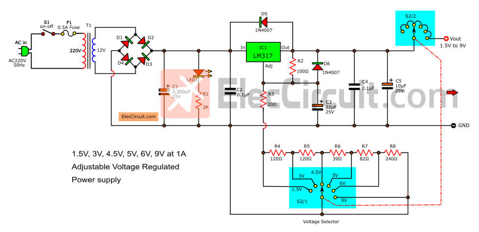
When we push power switch (S1) on, the AC-line voltage will pass through a fuse F1 and come to transformer T1 to reduce AC volts down to 12 volts.
Then this current flow through the bridge diode model (D1-D4)-1N4001 to full-wave rectifier as DC current.
And through C1 to filter current to smooth up and has C2 filter ripple signal before into LM317.
Learn: How to use LM317 Datasheet pinout and example circuits
LED to display power on the circuit, with R1(2K) currents to reduce it.
Here is the step-by-step process.
- The output voltage is determined by rotating a selector switch S2 a level voltage 1.5,3,4.5,5,6,9 volts respectively.
- C5 (10uF) control impedance and reduce a transient at the output of IC1
- C3 (10uF)- help to reduce the ripple before it is amplified when the output voltage rises up.
- C4 (0.1uF) reduces the ripple at the output.
- D5 and D6(1N4001) for protects IC1 from the discharging of C3 and C5 respectively. In case the input of IC1 is shorted.
The maximum output current about 1.5A depends on the size of the transformer. We should choose the size of the 2A. Or size 1A. For those who want to 1A output current only.
You may also like these:
- LM350 adjustable voltage Regulator
- 7805 Voltage Regulator
- 9 ways to build 24V power supply circuits
- High Current 12V-13.8V at 30A,25A,20A,15A Power Supply
How to build this project
This project is not used many components so can assemble on the universal PCB board. But can make a PCB as Figure 2.
Then, the wiring for circuit wiring and various components can view of the example in Figure 3.
What to look out carefully for is the polarity of the electrolytic capacitors and Diodes correctly. The pin of the IC is not an error.
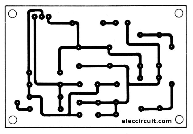
Figure 2 the PCB of this projects
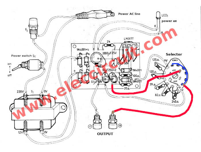
Figure 3 the components layout and wiring to all parts
Others of LM317 voltage selector
Also, you may like these projects below:
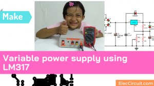
My first Variable DC Power Supply, 1.2V to 30V at 1A using LM317
It’s easy and as cheap as possible.
0-60V/0-30V DC variable power supply using LM317 & LM337
It is high volt and starts voltage at zero! good job.
Best 3A DC power supply, adjustable 1.2V to 20V, 3V-6V-9V-12V
High current for all circuit easy to use. Read more>>
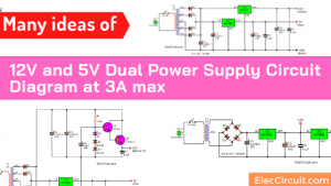
Dual power supply 3V,5V,6V,9V,12,15V with LM317,LM337
There positive and negative voltage output for all circuit easy to use. Read more>>
GET UPDATE VIA EMAIL
I always try to make Electronics Learning Easy.
Related Posts

I love electronics. I have been learning about them through creating simple electronic circuits or small projects. And now I am also having my children do the same. Nevertheless, I hope you found the experiences we shared on this site useful and fulfilling.
please send mi all project power switching tanks
Hi, shahin
thanks for your comment.
Please find power supply switching on mysite better.
or get email news member You can always learn new circuits.
Hi,thanks for your comment.your website is beter.
good lack
Hi, Jozef
Thanks,
Your welcome.
can u give me a design and a pcb layout of short circuit protected power supply with IC that has a 5v as an output?
please send me the correct cct diagram early
Hi, ivan
Thanks for your feedback,.
LM317t have short circuit protection.
Hi
Thanks for your feedback.
On the circuit is correct.
Sir, its John from the Philippines, What if I want to add 12v and 15v output? What resistor do I need add to work it? Pls. Tell me sir I’d love to do this… Thanks
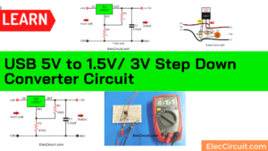
sir can u please suggest me a 5v dc to 1.5 dc converter?
hi.tanks for god informations.
can you send mi all project power switching? tanks
Thanks very good websit.
Hi aftab.
Thanks for your feed back.
why is it that the 20ohms resistor getting burned, how many watts resistor should i use, thanks
Hi, rod
D6-1N4002 may be connected to the wrong polarity. or switch direct current to R-20 ohms.
Please check parts again.
Good luck.
Hi there. I built a very similar supply for my self many years ago. Suggestion for you, make sure the selector switch is a ” make before break” type. If it is the more common break before make, then as you change the voltage selector from one setting to the next there is a brief moment when it is open circuit. This results in the maximum voltage being present on the output for a moment too. I destroyed a low voltage circuit on my unit ( maximum voltage 18v) switching from 3 to 4.5v You might need to shop around to find a make before break type. But I’m sure the bigger suppliers ( RS or Element 14, etc) will have them. Well worth the little extra money.
So this is interesting- with electronics, I know enough to be dangerous, so ¿¿ if I want to reduce a ~6.0 -7.4 volt input to 3.6 – 4.2 volt usable output, is a ‘completely’ different story yeah?..but not so complicated, how will I achieve this?…and thanks for the output, duTch
the selector Switch can be replace by Potentiometer?
The Selector Switch can be replace by a Potentiometer?
Buen dia.
Tengo una F.A variable con el LM317, de 1,7 a 27 vc., como sabemos nos da un máximo de 1,5,Amperios;como puedo hacer para agregarle más corriente (hasta 3 Amperios), se que se le puede agregar una resistencia y un transistor de potencia.
Les estaré muy agradecidos por su respuesta.
Can you post the list of all the parts? Thanks in advance!
Hi Bryan Siyang.
Thanks for your feed back.
Yes we will do it.
When you are switching a voltage from one to another, the rotary switch will end up in middle position for a short undefined period of time, which might (will) f*ck up the whole thing, and potentionally might burn circuit, since R3 will be floating, and as a result LDO will give out a high voltage spike.
So, a question: how can I implement a protection for this without redesigning a circuit for having a parallel (to rotary switch) resistor?
Hi Andrejs,
Your question is very interesting. You are observant.
Right now I can’t answer your question perfectly.
But I have experience. When I twist the switch halfway between the 2 voltages, it causes high voltages at the output. So we have to unload the load first.
Your point is interesting. I like it a lot. If you can design it then Please don’t forget to share with me.
It won’t be too hard to change the resistor values around to give me 7.2, 8, 9.1, 10, 12, 15 & 18 volts and add a negative regulator to give the same voltages -7.2, -8, -9.1, -10, -12, -15 & -18 volts on a negative rail. Generally I will be using +9.1 and -9.1 or close to +9.1 & -9.1 volts. For some reason some of the guitar & audio effects I use sound better with (a) dying battery(ies), so I have used 6 to 8.5 volts to feed effects that were designed to run off 9 volt batteries.
Hello Seth Burgin,
It’s a good sharing experience. This circuit produces good results, similar to using a 9v battery.
Thanks a lot.
As for the high voltages on the output that occur in between switching the voltage settings there are some simple tricks with properly selecting rotary switches that work quite well, such as specifying and using a “make before break” switch so the two settings will be shorted together before the other original setting’s circuit will “break” open. With a break before make there is NO resistor in the circuit at all in between settings. There is another unrelated simple trick with circuits that would discharge a capacitor & damage something where a ground is selected and MADE before the next circuit is switched on. This would effectively discharge any caps that might blow up an op amp or other linear chip.
Yes, when changing the voltage SW2 is open, the output voltage is highest. may destroy the load
Thanks for sharing your experience about discharging a capacitor & damage something.
I’ll talk to my daughter again. Shall we try this circuit? It’s very interesting. I like the power supply circuit. LOL
Your table shows R1=220 and R2=390 gives 3.35V
but the same resistors 6 lines below that gives 3.47V
Hello, dear friend!
Thanks for the correction.
We have already rewritten this calculation of LM317.
https://www.eleccircuit.com/lm317-voltage-regulators/
God bless you.