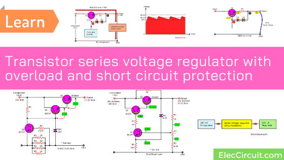
Do you like to learn about the work of the power supply circuit? I love it. Are you the same as me? I am going to tell you about the transistor series voltage regulator with short circuit protection.
I believe you understand the basics. And read relevant content previously.
Ready to get started?
How do filters ripple work?
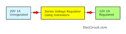
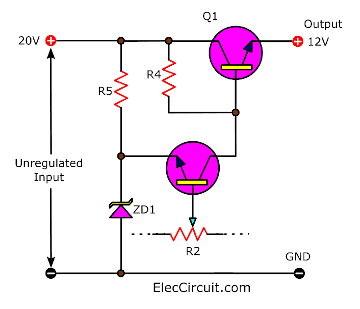
Imagine that we have 20 volts of DC unregulated supply sources. But our load requires 12V DC regulated voltage.
So, we need to use the series, voltage regulator. See the block diagram.
We know that you do not like any ripple voltage on the power supply.
From other previous articles, we found that any ripple appears on the 20V input. It will rise with the input voltage, 20.1V, or 20.4V.
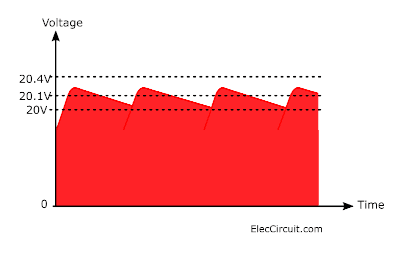
This increased voltage does not affect the Zener diode. Because it has a fixed breakdown voltage of 12V. So, the Zener is our base reference voltage.
Then, the error transistor-Q2 acts to sensor this increased voltage.
How it works
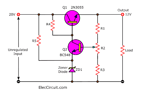
I am frustrated because I cannot explain it to you easily. But I will try to do my best. Here is step by step process. Look at the circuit diagram above.
Suppose that the 0.1V or 0.4V ripple passes through Q1. Then, its output voltage is 12.1V to 12.4V. Because of 12.0V + 0.1V Or 12.0V + 0.4V.
Next, R2-potentiometer senses the output voltage. And It will be set to partially turn on Q2. It makes the circuit gives the original balance of 12.0V.
The output appears the 0.1V ripple more difficult. The voltage on the collector will reduce. And this will turn Q2 very slightly. The emitter will follow the base voltage. But It is about 0.6V less.
This works very rapidly and can follow a ripple of fairly high frequency. So that reduces the smoothing output a ripple less.
If there are some ripples like a 2V p-p. This may improve it to 20mV at full load. Is it a good sound? What is more?
If we turn the circuit new. It looks similar to an emitter-follower form. Look:
The emitter of Q1 will always be about 0.6V less than the base.
In this circuit layout, it may be clear to see how Q2 runs like a variable resistor between collector and emitter. To provide a base voltage for Q1.
When Q2 acts like a low-value resistor. The base of Q1 connects to the cathode of the 12V Zener.
It then provides an output voltage of 12V-0.6V = 11.4V. When Q2 is a high resistance the base of Q1 is connected to the 20V input. And the output is 19.4V.
In real working, Q2 does not run this wide a range.
But this circuit has one slight disadvantage. It has no overload protection or short-circuits protection.
In the next circuit, we will try to fulfill these conditions.
LEARN: Relationship Between Current and Voltage
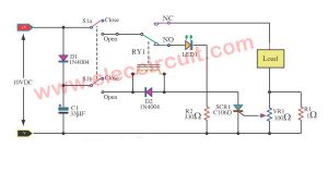
Series Regulator with short-circuit protection
This circuit provides short-circuit protection. If the output is shorted to ground. The regulator will shut down leaving R4 as the only source of supply.
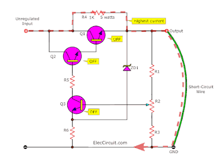
This state will not have any current flowing through R1, R2, and R3. So, there is no voltage across them. And no current to the base of the Q3 transistor. It does not conduct currents. And finally, Q2 and Q1 do not run, too.
For this reason, we should use the R4 to be a 5 watts wire-wound resistor. Though it does not supply any current in the power supply is operating correctly.
The only other time, the R4 is needed for the staring up. It must provide about 1V into the output to start up the circuit.
The set output pot(R2) detects about 50% of the output voltage to begin to turn on Q3.
Recommended: Learning electronics for beginners
Then, this will turn on the power driver transistor Q2. And, it will turn on the power regulator transistor Q1.
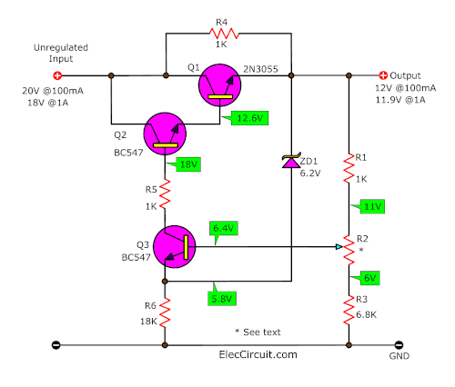
This condition will increase and stabilize with the output at 12V. And about 100mA load current.
Next, when the load increases to 1Amp, the output voltage reduces to 11.9V. This effectively increases the base-emitter voltage of Q1 to 0.7V to turn it on harder.
The input voltage may reduce by 2V or so. But the base voltage of Q1 will remain stable at 12.6V.
The parts you will need
- Q1: 2N3055, 100V 15A, NPN transistor
- Q2,Q3: BC548 or equivalent, 45V 100mA NPN Transistor
- R1,R5: 1K, 0.5W Resistors
- R2: 3.3K to 5K POT(potentiometer)
- R3: 6.8K, 0.5W Resistors
- R4: 1K 5watts Resistors
- R6: 18K 0.5W Resistors
Overload Protection
The two previous circuits have the advantage of about two-thirds of a good power supply.
They provide smoothing and regulation. And the 2nd circuit also has short-circuit protection.
Also, let’s see the 3rd circuit. It has an important feature to build into a power supply is overload protection.
Now, we will learn the feature limiting the maximum current rating of the power transformer and the power transistor.
In a short time, the output will be a maximum of up to 10 times the normal current. This causes overheating and damage to many components.
The overload protection should always be in power supplies that give more than 1 Amp.
Not only that it also prevents possible fire risk and reduces further damage to the equipment being supplied.
We may put them into two different forms.
- Fuse and circuit breaker
The simplest is using a circuit breaker or fuse(cheap) in the output. This will blow when the current rise approx 30% over the recommended max.
When it runs, the circuit will not reset itself. We need a manual reset or replace the fuse.
The obvious disadvantage with this is the inconvenience of physically changing the fuse.
Another way we can use electronic overload is better. - Electronic overload Protection
Read more below:
Overload Protection using Diodes
To protect a series regulator from excessive current overload. We can add the 3 components shown:
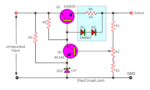
The 1 ohms resistor is in series with the output. So that all the current flows through it. As the current increases, a voltage will change across the resistor as ohm’s law.
Turning the circuit around will make the overload protection easy to understand as follow:
- The output current is 100mA at 11.99V voltage.
- The voltage at the base of the transistor is 12.6V.
- And the Emitter voltage is 12V.
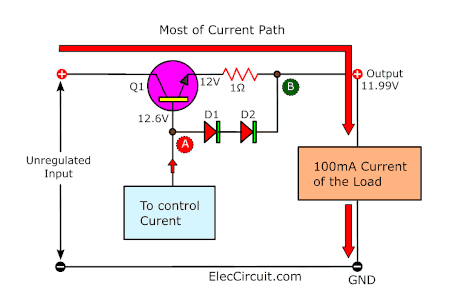
- Look at the A-B point. The most important point that we should know, the diode in a forward bias situation will drop a maximum of 0.6V.
Diodes help steady voltage
At two diodes the maximum voltage they will allow to be developed across them is 1.2volts.
This means the maximum voltage between points A and B will be 1.2 volts.

Do you understand? If you said NO. Read more examples it will help you get an idea.
Let’s increase the current to 500mA:
It looks like previous one. The output voltage is lower than the 200mA load. It is 11.5V.
Why?
The voltage drop across the resistor 1 ohms changes.
VR1 = I x R
= 0.5A x 1 ohms
= 0.5V
Look at the circuit diagram. Its output current increased at a slightly reduced voltage.
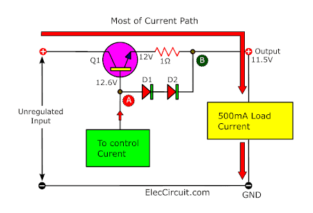
At 500mA the voltage between points A and B has increased to 12.6-11.5=1.1 volts.
This is still below 1.2 volts and thus the diodes do not have any effect at this current flow.
550mA Current to lower output voltage
When we use the 550mA current of the load. The voltage levels are shown in the diagram below.
The transistor turns on slightly harder to deliver the current. and this has produced a voltage difference of 12.7-11.45 = 1.25 volts.
Now, these diodes limit increasing the current will lower the output automatically. You see the diodes are helping as the voltage across them does not over 1.2 volts.
The voltage difference between two points(A-B) can never exceed 1.2 volts. Because of the clamping effect of the two diodes(D1, D2).
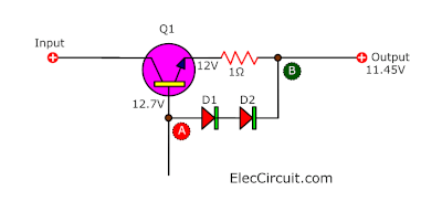
Any increase in current will be lower the output voltage (Due to the voltage drop across the 1 ohms resistor).
But this voltage will pass straight back to the base via the diodes. And this will turn the transistor off. This will give a lower output voltage.
The net result will reduce the output voltage. so that the maximum current flowing will not exceed 550mA.
As you know ohms law. A lower voltage applied to the load will result in a lower current flow
Short-circuit protection using Diodes
Let’s learn the case of a short-circuit:
Do you know what is the main disadvantage of the previous overload protection? Yes, we can see. Some voltage drop needed to operate the sensing circuit. From no-load to full-load, reduce to 0.5V voltage.
Look at the circuit This point A will has down to 1.2V. And, the emitter will appear at 0.6V. At point B is 0V. The current in the short circuit will be 550mA.
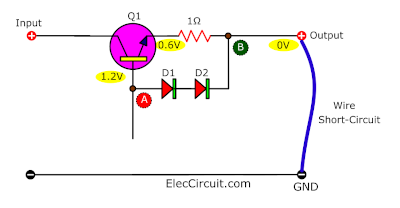
We will see that this is easy. But its stability is not good enough for some equipment.
For example, the TV set. Some sets require a supply voltage of only 11 volts. Even a change of 0.2 volts, will run a lack of width or height. So, imagine the effect of 0.5 volts. How is it?
Read Other: series voltage regulator with short circuit protection
When the varying brightness levels, it will require the altered current and change in voltage, too.
How to improve it?
Overload protection using transistor
Do you ever learn about a current limiting circuit?
Yes, I used to tell you:
We can place it on the input side of the pass transistor. Where it will have the least effect on the output voltage.
Look at the following circuit show this circuit:
This is a 13.8V 2A voltage regulator circuit using the transistors
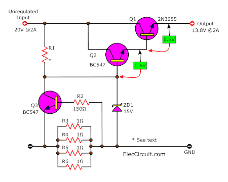
- Q1 is the series pass transistor.
- Q2 is a sensing amplifier
- Q3 is the overload detector.
Even if the circuit looks easy. But understanding it is a challenge.
First, the input comes to R1 to Zener diode, reference voltage. And the bleed current (see the previous presentation for this).
Then, The Q2 serves to amplify the voltage. It detects on its base to supply Q1 with the required current. Because Q1 will need at least 20mA base current and possibly more like 50mA.
Read also:
- Simple Overload protection circuits
- How does a transistor circuit work
- Learn voltage divider circuit works with rule and calculating
This allows the Zener diode to have a lower bleed current.
Under normal conditions, Q3 turns off and plays no part in the operation of the circuit.
Look at the basic circuit zoom at the Q3 circuit.
The 4 1 ohms resistors in parallel combine to form a 0.25 ohms resistor.
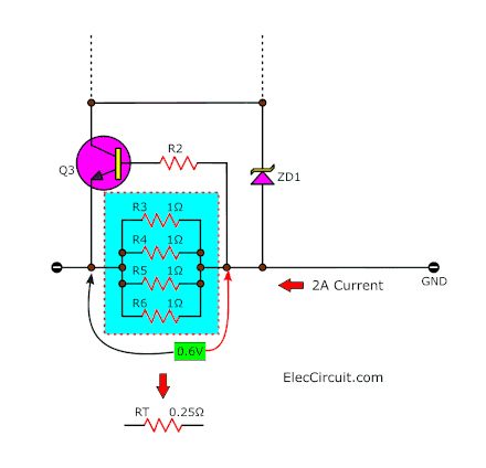
And when the current approaches 2 amps. A voltage of 0.25 x 2 = 0.5 volts will develop across the combination.
This begins to turn on in Q3 and if the current increases further Q3 will turn on fully. It will short out most of the Zener diode voltage.
Then, the base of Q2 will see a voltage as low as 3 to 4 volts. The emitter of Q2 will follow this fall with a voltage on its emitter of 2.4 to 3.4 volts. The output of Q1 will reduce to 1.8 to 2.6 volts.
If this can keep the low voltage in a short-circuit condition. The circuit will remain in this shut-down mode. This may protect the equipment.
Of cause, this circuit is not the best. We can improve it by learning more.
Parts you will need
0.25W Resistors, tolerance: 5%
- R1: 470 ohms
- R2: 150 ohms
- R3 to R6: 1 ohm 1 watt. Resistors
Q1: 2N3055, 100V 15A, NPN transistor
Q1-Q2: BC5487 or equivalent, 45V 100mA NPN Transistor
ZD1: 15V 1W Zener Diode
Credit: I learned how they work from The Talking Electronic No.8 Thanks a lot.
Check out these related articles, too:
Power-Loss in a series regulator
In the series pass transistor regulator. The Q1 power transistor feels Suffered a lot. We can help it gets healthier. Because there is still much more detail. If you are interested in it, read more: Power-loss in a series regulator circuit.
Download This Post
All full-size images and PDFs of this post are in this Ebook below. Please support me. 🙂
GET UPDATE VIA EMAIL
I always try to make Electronics Learning Easy.

I love electronics. I have been learning about them through creating simple electronic circuits or small projects. And now I am also having my children do the same. Nevertheless, I hope you found the experiences we shared on this site useful and fulfilling.

Very Clear Explanation
Hello Rick Hodgson,
Thanks for your feedback.
Hello Gloin,
I am cheerful that you saw my efforts.
I thank you for taking the time to guide my mistakes.
And I will try improve your English.
Hope you can help guide the easy practice methods for me.
Circuit discriptions are understandable. Thank you for effort. Best wishes .
Thanks for your feedback.
Explicación muy clara y amena
thank you. My dad and I will continue to make content like this.:)