
This is a Simple Power Supply for Audio Amplifier circuit. It is a simple fixed regulator. Which there are multiple output voltage of 12V, +15V,-15V,+35V,-35V and Dual up to 70V max. They use principle working of Zener diode and IC-regulator as base for steady voltage output.
It is ideal for 50 Watts to 60 watts OCL power amplifier. This Circuit is Small and low cost and easy working. You may like it!
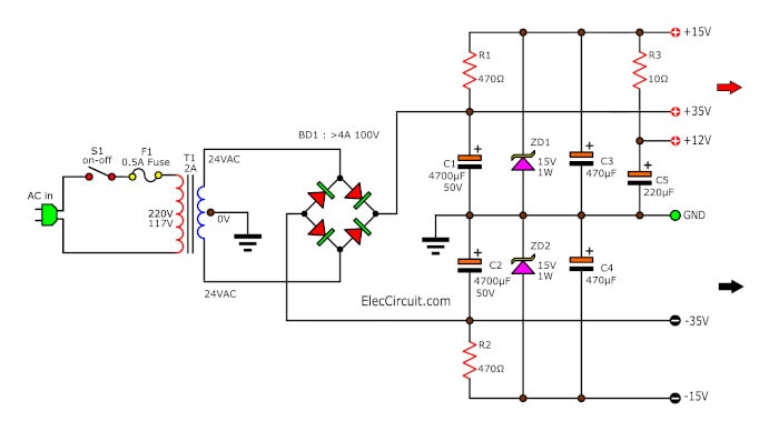
Figure 1 : Power Supply for Audio Amplifier circuit Dual voltage 12V 15V 30V
Recommended: How to use Zener Diode, example circuit usage
The Working of Circuits
The simple power supply uses base components that are Zener diode, Resistors, and capacitors. It performs the equipment to maintain stable voltage or regulated.
They consists of step-down transformer T1, rectifier bridge (D1,D2,D3,D4) and a filtering regulator circuit made up of C1,C2,C3,C4,C4,C5,R1,R2,R3,ZD1, and ZD2.
When AC line is applied to the transformer T1 changes 220VAC to about 48VAC in the center tap(CT).
Then, the rectifier bridge rectifies the AC into pulsating DC. Next, the DC current is filtered by C1, C2.
Both capacitors act as storage capacitors or filters to smooth DC.
Now voltage at this point is +35V,-35V(for main power amplifier)
Then, the DC unregulated flow to R1, R2 to ZD1, ZD2. They provide a reference voltage at the output can have voltage get +15V, -15V (for pre-amplifier circuit).
And some current flow to R3 reduces the voltage to 12V for the pre-mic circuit
Note: You can see a lot of circuits about simple 12v power supply circuit
Parts you will need
- T1_24V CT, 3A Transformer; Quantity = 1
- ZD1,ZD2_15V 1W Zener Diode; Quantity = 2
- C1,C2__4,700uF 50V Electrolytic Capacitors; Quantity = 2
- C1,C2__2,200uF 35V Electrolytic Capacitors; Quantity = 2
- C1,C2__2,200uF 16V Electrolytic Capacitors; Quantity = 2
- R1,R2__470 ohms 1/2W Resistors tolerance: 5% ; Quantity = 2
- R3__10 ohms 1W Resistors tolerance: 5%; Quantity = 1
38V and 15V Preamplifier Power Supply circuit
What is more?
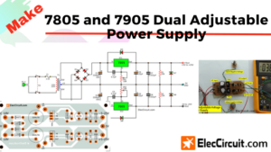
This is 60 watts amplifier Power supply circuit.
Sometimes you use a great preamplifier circuit. It requires a stable regulated power supply. Just only Zener diose is not enough.
How to do? Look at:
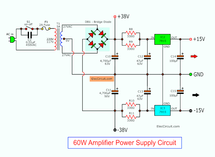
We use the 7815 and 7915 Regulator ICs. Both ICs are nice parts.
Note: Watts of R8 through R11 are 1 watts to 2 watts.
Parts you will need
- IC1: LM7815, 15V 1A Positive Regulator
- IC2: LM7915, 15V 1A Negative Regulator
Electrolytic Capacitors - C10,C11: 4,700uF 63V
- C12,C13: 47uF 63V
- C14,C15: 100uF 63V
Resistors tolerance: 5% - R8,R12: 330 ohms 1-2W
- BD1: 6A 400V Bridge Diode
- T1: 24V CT, 3A Transformer
- C2: 0.01uF 400V Ceramic Capacitor
- S1: ON-OFF Power switch
Read next: This 60 watts power Amplifier circuit
Choosing components for power supply
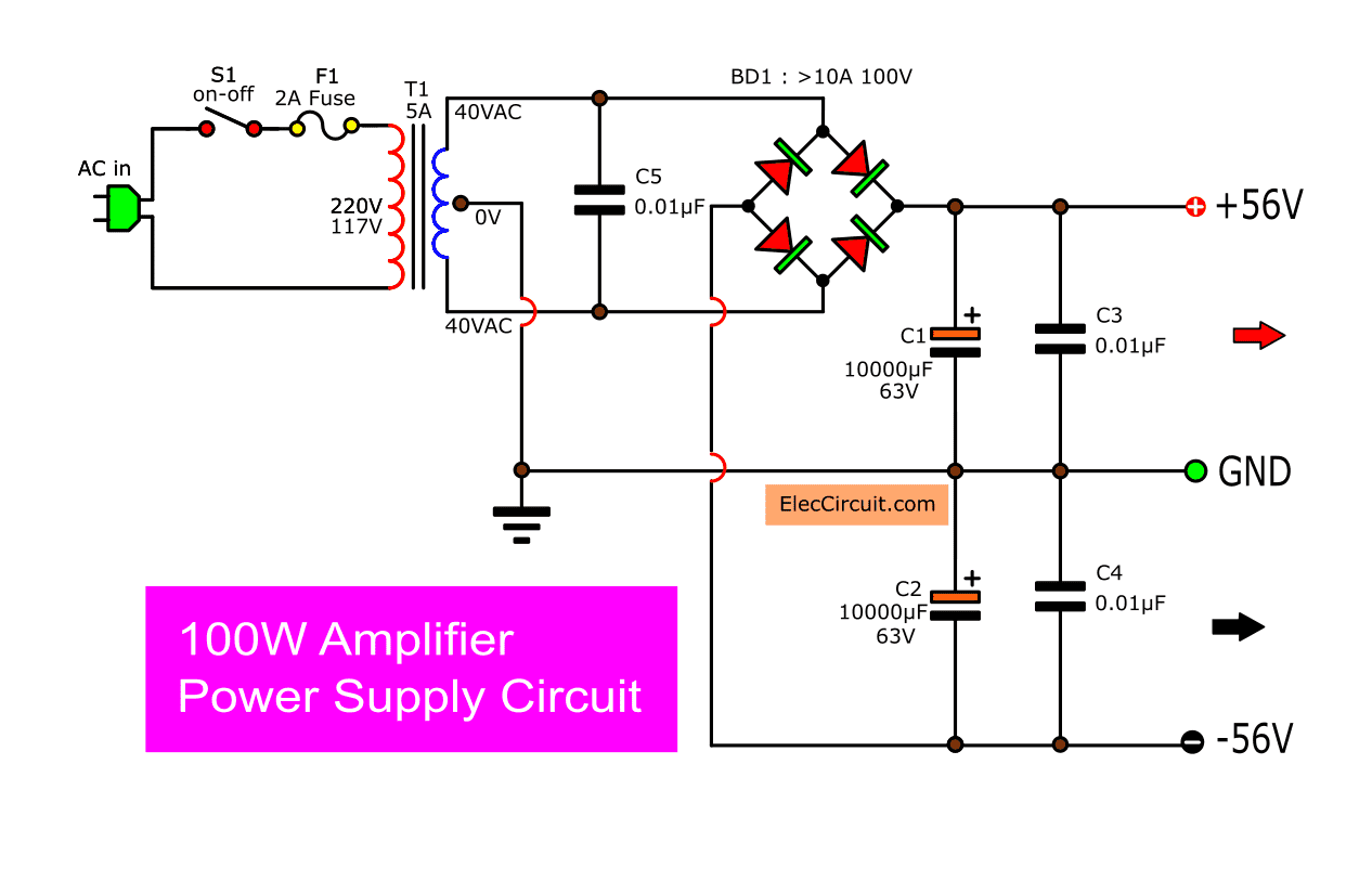
There are friends wondering How do we choose electronics for 100 watts power amplifier?
In this era, we need to save money. We therefore only need to use the equipment worthily and absolutely necessary.
I would like to recommend the following guidelines for choosing equipment.
- Is there enough current transformer?
In normal amplifier has approximately 22 times of gain. When the input voltage is 1V. So, the output voltage is 22V. When using Ohm’s law.
P = VxI or
I = P/V Try it!
I = 100W / 22V
= 4.5A or We use 5A transformer for Mono/10A for stereo.
If you use a lower current. It may reduce the sound power. When he opened the volume a lot. - How much is the capacitor filter?
According to my experience, I often choose the capacitance of the capacitor filter according to the size of the transformer. It is easy to find. 1A per 2,000uF.
For example this case 5A x 2,000uF = 10,000uF
Read more: Why should it enough
Sometimes you can use more capacitor connected in parallel to increase capacitance more. For example, we have 4,700uF x 3 = 14,100uF.
But be careful!
But having to consider the minimum voltage that can be tolerated. For example, the one with the lowest voltage of 50V. It shows that they can withstand the only 50V.
According to my experience, I often choose the capacitance of capacitor filter according to the size of the transformer. It is easy to find.
1A per 2,200uF.
Parts you will need
- C1,C2: 10,000 uF 63V Electrolytic capacitors
- C3,C4: 0.001uF 100V Mylar Capacitors
- C5: 0.01uF 100V Mylar Capacitor
- T1: 117V/230V AC primary to 40V-0-40V,5A secondary transformer
- BD1: 10A 100V Bridge Diode
Amplifier power supply using High Current Transformer
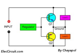
This is an amplifier power supply circuit. We have a good idea to solve there is not enough electric current.
This circuit connected a much high power transformer with a parallel circuit. So cause we have the output current higher than normal power supply circuit.
The Working of power supply circuit
The transformer has many coils. We can bring to do a high Current power supply circuit well. By if all coil has Voltage be equal.
It is can bring parallel can follow this circuit is coil lead that has Voltage 24V and has Current about 1A comes to parallel prevent all 2 the group.
See: Many 24V Power supply circuits
It has current altogether in each 2A group by having voltage at 24V be the same.
This circuit then can become a Dual power supply at 34V positive and -34V Negative and Ground. This circuit is used to ensure that the amplifier power supply is good. Suppose will give the electric power about 50 watts.
Learn more: Designing 12V 5A Linear Supply and Other circuits
For the diode use 3A 100V sizes. And use the Stancor (a type of inductor) filter noise signal the all well. This circuit may help to give testimony and have the idea in applying work others.
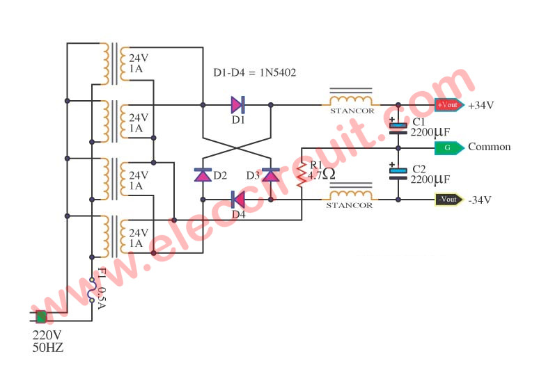
Figure 1: Amplifier power supply using High Current Transformer
Other Circuits
Not only that. See more about amplifier power supply circuits below:
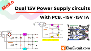
Preamplifier Power supplies
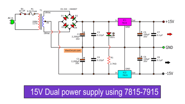
Dual 15V Power Supply Schematic With PCB, +15V -15V 1A For Pre Amplifier circuits. We use transistors, Zener Diodes, And IC-7815, 7915. Easy to builds with PCB layout.
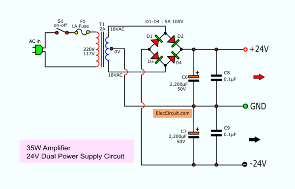
24V Dual Power Supply Circuit
For 30 watts to 35 watts OCL power amplifier circuit. You can use this circuit below.
31 Dual Power Supply Circuit
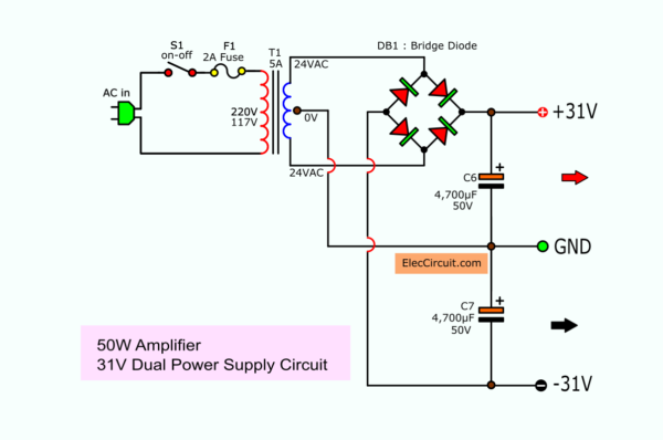
For OCL Amplifier in 55 watts power. Read more
GET UPDATE VIA EMAIL
I always try to make Electronics Learning Easy.
Related Posts

I love electronics. I have been learning about them through creating simple electronic circuits or small projects. And now I am also having my children do the same. Nevertheless, I hope you found the experiences we shared on this site useful and fulfilling.
please can you help me to realize 5VDC power supply from 220v ~
Hi. My name is aziz, i am from Afghanistan, your website is very good
Hello, I have been looking for a project of a powerful Battery Eliminator Circuit with its pcb layout and other details for its construction, the power output ranging from 1.5 to 12 or 15V DC, I will be very thank full to you if you can provide me the same. And also if there are any instruction to follow in building the eliminator or taking care, it will be very help full. Thank You.
Thanx sir but in 60w preamp power supply how is the power of R8-R11
Hi Ness,
These resistors is 1watts to 2 watts.
I’m glad you are interested in this circuit.
Hope you enjoy electronics.
With Fig.1 Schematic, can i suppy 100W amplifier ?
Hello Mufid
Thank for you answer.
Please read again: https://www.eleccircuit.com/power-supply-for-audio-amplifier-multiple-output-12v-15v-35v/#Choosing_components_for_power_supply
Hello friend, You do a great job informing and helping people interested in these projects, that´s very nice.
I just have a little doubt, on the 38V and 15V Preamplifier Power Supply circuit, for what I see, the transformer outputs 27-0-27vac at the secondary, how did you ended up getting 38-0-38vac?Thank you very much…
Hello Wilson Nogueira,
Thanks for your visit, my friend. You are welcome.
Let me explain to you. In normal unregulated power like that the DC output is more than AC input 1.4 times.
When it is 27VAC, the output is 37.8V or about 38VDC. I’m not sure, Have you read this?
https://www.eleccircuit.com/unregulator-power-supply/
It might give you a clearer.
Thanks again
Hi, I would like to ask what specific diode we can use for the Fullwave Bridge rectifier 5A 100V. Thank you.