Do you need to use a 9V battery? But you have a 12V battery only. We have many how to convert 12V to 9V. Now I will show using 2 circuits ideas.
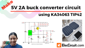
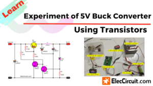
Though this circuit uses just two transistors and others 8 components. But it is the well-regulated power supply. We use it as the simple step down 12v to 9v converter circuit. It can give the output current up to 4A. Also, there is overload protection. When we use too many currents, the output will reduce the current down.
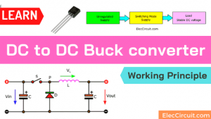
How it works
To begin with, enter the input voltage, 12V into the circuit. The R1 passes the current at positive in two ways. First, to output, 9V with low current. Second, through D1, D2, R3, and VR2 to the ground.
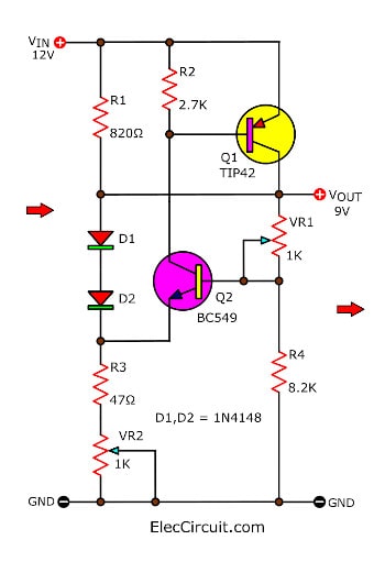
Since there is the voltage drops across D1, D2. So, the emitter of Q2 gets the biased current with the voltage lower than the output 1.2V, all the time. The voltage drops across D1 and D2 are the reference voltage of the circuit.
This output voltage will rise. While the emitter voltage tries to rise to be the same rate. Which it gets base current from the voltage divider circuit, VR1, R4.
The base-emitter voltage will try to reduce. And Q1 stop working. So the output voltage is low down.
If the output voltage is reducing. The circuit will turn working in the opposite way.
The base-emitter voltage of Q2 will rise, it is more working. Which causes Q1 more work too.
Thus the output keeps voltage is constant again.
When the output current rises up. The current flows through Q2 rises too. Which causes the power transistor-Q1 more works. And the current flows through R3, VR2 is higher, too.
But the current flows D1, D2 to reduces down. This causes Q2, Q1 comes back to low working again. Thus the output voltage is low voltage, too.
The average hFE of The Q1-transistor, BD242 is about 25. It makes the maximum output current is 4A. We can adjust the current with VR1, in 0.2A to 4A range.
The VR2 provides adjustable voltage for the output.
This circuit is small. I hope you are fun with it. If you have tested it gets a result, do not forget to share with me.
Recommended: 9V power supply circuits
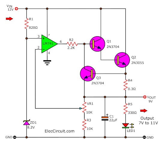
12V to 9V 2A step down dc converter using IC 741 and 2N3055
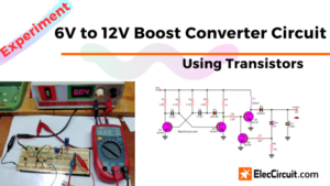
This circuit designs for modifying a 12V power supply input 12V from a battery or the other. Have the level voltage be down be left 9V be stable or , 9V at 2 Amp DC power supply.
By this circuit gives usual equipment, seek easy. Be integrated circuit IC 741 and power transistor 2N3055. Besides this circuit still can find to differ out voltage with well and have picture stability although load modifies. The Zener diode 8.2V be formed fix stable reference or voltage the referable at pin3 of the integrated circuit and, the VR1 is fined the level volt output.
Power Supply 6V-9V for a calculater
The circuit that sees this is the power supply 6V to 9V (Input 12V) of a calculator. That has to prevent something through the circuit. The part that performs to heal strong a picture uses the integrated circuit op-amp multi-purpose 741 numbers in the character comparator mode.
How this circuit works
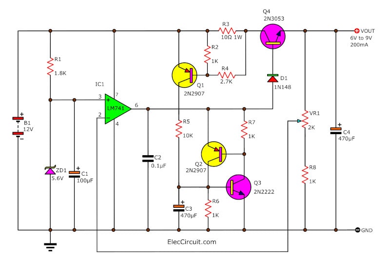
The circuit protects output compose transistor Q1-Q3. By transistor, Q1 performs acknowledge voltage straddle Resistor R3. Which work when have current about 250mA or more than flow through R3 when TR1 work pick load C3, as a result, will do way resister package R5 10K values and thereafter 2 railings second.
The voltage will enough encourage. Q1 which cooperates with Q2 assembles be Transistor many rapidities are only. This circuit consumes current in the condition calmly don’t arrive at 5mA and Current fully a part will protect to have 12mA railing sizes only.
Keep reading: Variable transistor power supply

Related Posts
I love electronic circuit. I will collect a lot circuit electronic for teach my son and are useful for everyone.
I just rewrite this article. It is a simple power supply circuit.
Hi
Must there be an load for the 9v output, when testing the circuit my labsupply goes in protection ? Seems to be a current of 0.1 A all the time floating thru.
Hi dear friend,
We are happy that you like these circuits.
We love to test the power supply circuits.
But these circuits have never been tested by my daughter.
Yes, you should have a load to test it. we will measure the real output voltage.
It is well new that you will test them. We will wait for your sharing.
God bless you.
Apichet and kids