Here is a 7805 Adjustable voltage regulator circuit. I recommend many projects that use IC-7805 or 78xx types. Today, it will modify from the old circuit, IC-78xx series has many numbers.
We can choose the desired voltage. such as “12V” should use IC-7812, but sometimes we don’t have this number for any reason. But we have too many IC-7805 numbers since it is applied often in digital circuits.
And with the reason above, so it is cheaper than others and easy to look for in a store. Therefore, I think to apply the IC-7805 to adjust various voltage level, such as 7.5V, 8.4V, and 10V, etc.
Finally, it is this variable DC voltage power supply that can supply output of 5V to 22V at 1A
7805 Variable Voltage Regulator
With a habit of playing the circuit and setting up suspects in various circuits.
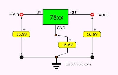
In this case, too. Firstly, Assemble components as the circuit in Figure 1, a negative lead. Then, use a digital multimeter to measure the voltage at various points. Appear voltage at the output and negative pin is about 16.6V and also measures current.
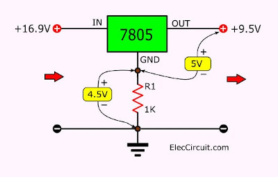
Release the pin negative and measure the voltage at various point Then, I take the 1K-resistor joint between the negative-ground pin as Figure 2.
And next measure the output of 9.5V.
The next measure across R1 has a voltage of 4.5V. After that measure the output-negative lead of IC1 same 5-volts that a steady voltage at all times.
It means that we begin to see the way. Thus, replace R1 with a 5K-potentiometer.
And then rotate it, can measure the output of 9.5 volts, cause voltage output during 5V to 14.8V. Show that IF put the resistor drop across between the negative and ground lead.
It can change output voltage and measure the voltage of the output lead compared with the negative lead of IC1 of 5V at all times.
A formula of 7805 variable Regulator
I always like to calculate the various devices. For ease of use.
When see in Figure 2 will see that the current flow through R1-1K will cause a voltage drop across it by around 4.5-volts.
Following the sequence, we came to the current flowing through it together.
The simplest and most obvious way is measured by an ammeter.
I measure current at about 4.6mA. Thus try instead of the value below:
R1 = VR1/IR1
VR1 = 4.5V , IR1 = 4.6mA
Results : R1 = 4.5V / 4.6mA = 0.98K ohms
The value was close to R1. But we are still inconclusive.
I replaced R1 with the potentiometer again. Then adjust voltage since 6V,7.5V,8V,9V,10V and 12V etc.
I found that all the voltage values have one current value flow the potentiometer same together is 4.6mA at all times.
Then we try to calculate the resistance again, We want to supply voltages up to 12V, we would have thought from the formula :
By: VR1 = VOUT – VIC
Set to: VOUT = 12V, VIC = 5V
Instead value :VR1 = 12V – 5V = 7V
Then replacement in (1) the formula :
R1 = 7V / 4.6mA = 1.5mA
Thus can find the resistance 1.5K replace on R1, the output appears to the voltage of 11.9V nearly well.
Conclusion is my the formula is R1 = (VOUT – VIC) / IR1.
Real 7805 adjustable voltage regulator circuit
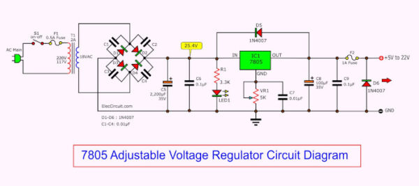
Next, we see a real use for me. It can adjust the supply voltage from 5V to 22V and under 1A. Which is enough for normal use of us. Figure 3 as the full circuit in the application.
7805 variable voltage regulator circuit
The concept for the device in the circuit
This 7805 variable voltage regulator circuit is nothing special, a Similar circuit ago.
So it is recommended only priority is device-specific:
1. T1 is a transformer to provide to the entire circuit, From the conditions of the circuit, we should select the transformer and 1A is sufficient.
And can use more than this, such as 2A. But it will be larger and more expensive.
Section voltage ratings are required to calculate it.
Determined from (Vout/1.4) +3 V, in when Vout = 22V.
Try to replace the value (22V/1.4) +3 V = 18.7V. I chose the 18V Size, which may be used as transformers 9V CT 9V (don’t use CT) or Use an 18V CT 18V (use only, 18V and CT lead, but 18V lead the rest not used).
The origin of the …
- 1.4 is a constant number. from voltage between DC and AC is the relationship between the VDC = 1.4 x VAC.
- 3V is the voltage value lost in the IC.
2. C5 is a capacitor that acts as a voltage filter. I calculated about 1,515 uF, but this value is without sales. Thus use 2,200μF 35V instead.
3. R1 is a resistor to reduce current to LED1. I calculated about 3.12 K and chose a value of 3.3k.
4. C7 is the capacitor that act as a noise filter from between the variable resistor-VR1. I select the value of 0.01μF 100V.
5. D6 is a Diode that acts to prevent the reverse flow of electricity to the power circuit, which may cause a damaged circuit, as mentioned above. In this circuit, I chose the diode type 1N4007 diode.
Build 7805 adjustable voltage regulator
First-order for the device to complete first. Details are as follows:
IC1: LM7805, 5V DC fixed voltage regulator or equivalent
D1-D6: 1N4007, 1000V 1A Diodes
LED1: LED as you need
C1-C4,C6,C7,C8: 0.01μF 50V, Mylar or Ceramic capacitors
C5: 2,200μF 35V, Electrolytic capacitor
C8: 10μF 35V, Electrolytic capacitor
R1: 3.3K 0.25W +5%
VR1: 5K Single Potentiometer type B
F1: 0.5A Fuse
F2: 1 A Fuse
T1: Transformer, 18V 1A
Etc.
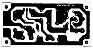
Further, makes the PCB layout as Figure 4 or use the universal PCB board.
Because of a few components and easy to build.
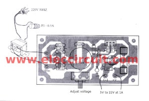
Then place the components layout as Figure 5 and wiring to the parts successfully.
Check the error to make good again, before applying the circuit.
What I want to warn, is to be careful about polarity electrolytic capacitors and diodes.
Should connect the voltage measurement lead.
Before the input voltage is fed, rotate the potentiometer-VR1 lowest. Before will have a voltage of 5 volts.
Then adjust voltage rises.
Many 7805 Circuits
What’s more? You can look other power supply circuits: Click Here
GET UPDATE VIA EMAIL
I always try to make Electronics Learning Easy.

I love electronics. I have been learning about them through creating simple electronic circuits or small projects. And now I am also having my children do the same. Nevertheless, I hope you found the experiences we shared on this site useful and fulfilling.



This is a Handy Dandy Little Circuit!! I May Build This One day..Many Thanks From MR.OHM!!
Many Years Ago I Designed A Voltage Divider In a LM317.I Designed It with A 6 position 1 Pole Rotary Switch Which Offered Me 6 assorted Voltages..Too Bad I Threw the Diagram away..Oh Well!!!Anyway Your design is AWESOME!!!
Your circuit is a disaster. It will have huge output voltage variation from part to part due to spread of current into the adj pin. You need two resistors. The correct circuit is all over the web and in many datasheets. My 50 cents
wow .. very nice and handy circuit
Hi Mr ohm 1970,
Thanks for your feedback.
My friend!
Hi leonidas,
Thanks for your feedback.
I tried this circuit works well. Although it does not meet a datasheet.
Hi asd,
Thanks for your feedback.
very nice circuit also your explained way to understand every components used in Circuit
Thanks
Thanks for your feedback.