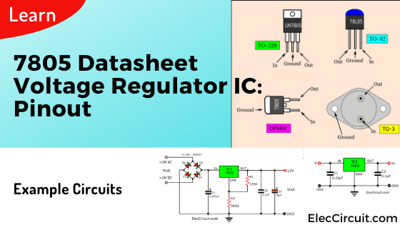
Here is the 7805 datasheet which is the popular 5V voltage regulator IC and the 7805 pinout.
It is designed to provide a constant 5V at 1.5A max when powered by 7.3V to 35V.
We usually use it as a stable voltage source for a common digital circuit.
Sometimes, the power supply using a transformer can have too high a voltage.
We should help lower the voltage by using The 7805, it can reduce and keep the constant voltage at 5V.
Therefore, It is good for powering the TTL family of digital integrated circuits.
7805 Datasheet
Basic Feature
- Typical output voltage: A typical 7805 delivers 5V. Some models may provide from 4.8V to 5.2V.
- Load regulation: The load is typically regulated to within 10mV and less than 50mV.
- Peak output current: The TO220 version of 7805 delivers 1A with a normal heatsink, but it could deliver up to 1.5A by mounting it to an appropriate heatsink.
- Internal overload and Short circuit current protection: If the 7805 regulator IC operates over too much and starts to overheat. A special thermal overload circuit will automatically turn off the chip until the temperature returns to a safe level.
- The minimum input voltage to deliver 5 volts output: 7.3V. below 7.3V the chip may not provide a stable 5 volts.
- The operating current (IQ) is 5mA.
- Junction Temperature maximum 125 degrees Celsius.
- Available in TO-220 and KTE package.
- Maximum input voltage: 30VDC, but at higher voltage, it needs to hold current and more power on itself. Therefore, it will become too hot.
Questions: If the input voltage is 24V. Will we be able to use the 7805 circuits? Or what regulator IC converts a 24V to 5V? Your answer is here.
Friends of mine
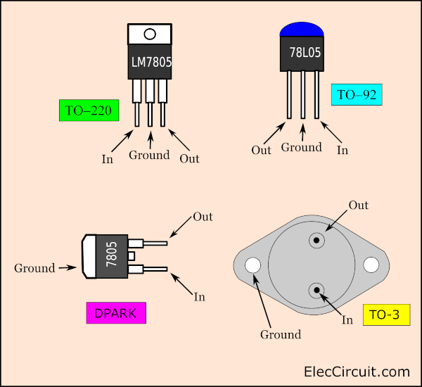
7805 Pinout and Specifications
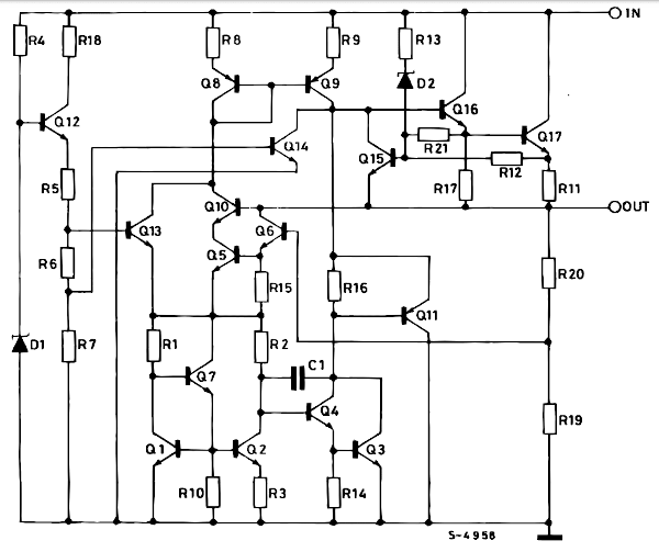
The 7805 has many components inside it, that are connected as the schematic diagram below. It is so many! In general use, we do not need to understand those components. We just by understanding its features and limitations to use it on a normal basis.
Compare to the simplest Zener diode and transistor regulator circuit with an input voltage of 12V and constant output voltage of 5V at 1A.
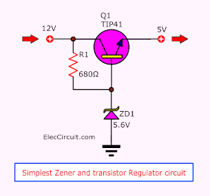
This works well enough for its job with a few parts, consisting of only a power transistor, Zener diode 5.6V, and one resistor.
But looking back inside the 7805, it has more components. Thus, it would be more efficient than the transistor version.
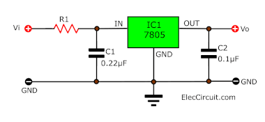
Basic 7805 regulator circuit
Look at the basic circuit diagram using a 7805 regulator. In 7805 datasheet said, C1 and C2 will keep the stability of the circuit. To reduce any noise, spike voltage, and more.
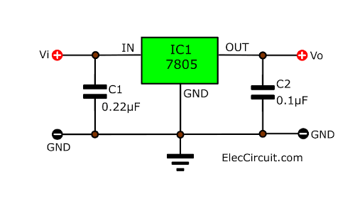
Basic 7805 Regulator circuit diagram
Actually, I have tried without the capacitors or only one IC. The circuit works normally.
Which one is better? Which one should you choose?
In my opinion,
if you need to use it on a common circuit and quickly. You may use it by itself. But if you need maximum efficiency(optimum stability and transient response) out of 7805, it would be better for you to use bypass capacitors (C1 and C2). We also put it close as possible to the IC.
Be cautious of 7805’s Pinout
The 7805 has various versions. The TO-3 version comes in an all-metal can for better heat sinking. A small plastic TO-92 version can provide up to 100 mA for low-power circuits.
At the present date, we will often see DPARK, since it is a small size. Therefore, it becomes suitable for SMD PCB work.
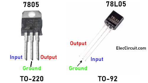
Look at these 2 popular types of regulator IC. Both differ in the current output:
- The 7805. (TO-220) — with 1A of current. I prefer it because it can supply enough current for normal use, is easy to install, and is cheap.
- The 78L05. (TO-92) — with 100mA of current. It looks like a small transistor, which is more suitable for use in small spaces and low current circuits.
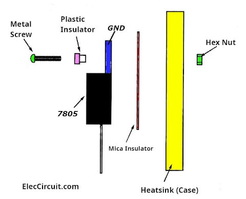
The metal plate at the top of 7805 regulators is also connected to the ground leg (GND). Therefore, you need to mount it properly through the hole with a metal heat sink as below.
3 Important things for 7805
There are 3 main keys, you should know about 7805 for smooth operation.
- The input voltage must be higher than 7.3V to keep the regulation. Higher the voltage is, the temperature will also rise up as well
- Enough heatsink — The simplest way to test the heat transfer of the heatsink, is to hold your finger on it for at least 30 seconds or so. If it is unbearable, then you should increase the size of the heatsink.
- Close enough wiring — Connection of capacitors to the 7805 regulators should be as close as possible to remove oscillations.
Read below for its practical use.
Circuit ideas that you can get useful
7805 Voltage Regulator Circuit
This voltage regulator IC can deliver many typical applications such as a fixed or adjustable voltage from an external power source.
Below are a lot of circuits. They may help you solve your problems.
Fixed Output Regulator
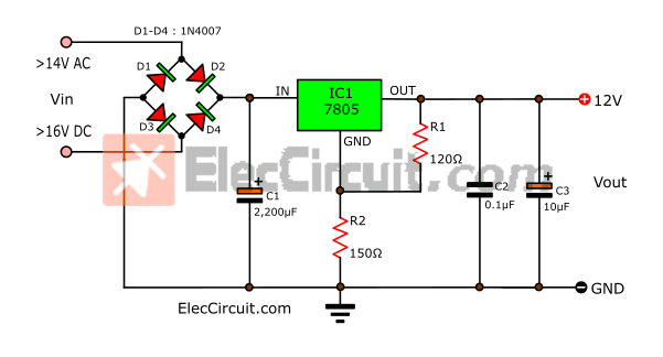
First, let’s take a look at a typical 5V fixed output regulator or 7805 power supply circuit.
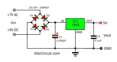
The C1 (2200uF) and C2 (0.1uF) capacitors must be mounted close to the regulator.
The input voltage must be higher than the output to allow for some voltage to drop across the bridge and regulator.
The minimum Vin for a 5V Vout is 7V AC or 9V DC.
Note: Any input AC or DC to the bridge will automatically adjust for correct polarity. It allows both connections to power the board.
Next are a typical 7805 regulator on a breadboard.
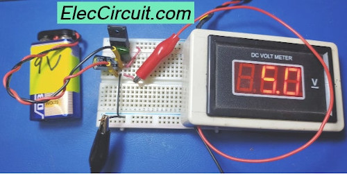
This open-type arrangement is only suitable for a very low output current since the 7805 is not heatsinked. We change C1 to 220uF 25V. Important, the 7805’s output needs to be close to the 0.1uF capacitor to prevent it from oscillating internally.
I want you more understand 7805 regulator circuit. So, seeing other sites may make you improve electronic Click HERE
That’s not all…
7805 variable voltage regulator circuit
Imagine you want the 12V power supply. But you have only 7805, how could you make use of it? Colin Mitchell once said the output voltage of a supply can be increased by jacking up. The circuit below produces an output of 12V with this method.
The 7805 always keeps a constant voltage at 5V between the output and the GND (common) terminal.
If the GND voltage is increased, the output voltage will also rise up. For example, if we increase the GND voltage by 4V, then the output voltage will be 9V (5V+4V). This method can give any voltage between 5V and 30V. It is a complete range of regulators.
We use two resistors in the “Voltage Divider Mode” to determine the output voltage. There are always 5 volts across the 120Ω resistor (R1). If a 150Ω resistor (R2) is placed in series with R1, it will have a proportional voltage across it.
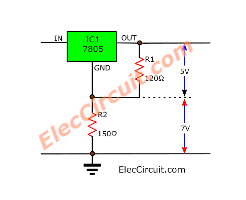
In the basic circuit diagram above, the voltage across R2 (150Ω) is 7V. It makes a total of 12V at the output.
To increase or decrease the voltage, only one resistor has to be changed in the circuit above. We will leave the 120Ω resistor (R1) alone then we are going to change the R2 resistor instead.
If we increase the R2 Resistor to:
- 220Ω — the output voltage will be 14V.
- 330Ω — the output voltage will be 18V.
By changing R2, it will produce an adjustable output voltage.
There are two things you should be aware of when using L7805 as an adjustable version.
- First, the 7805 regulators should be heatsinked so it is capable of dissipating the heat in the worst condition.
- In addition, the input voltage should be more than the maximum output voltage of about 3.5V
7805 output voltage calculator
The following formula is used to find the output voltage of the 7805 regulators.
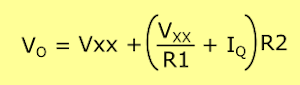
Note: Vxx = 5V, IQ = 0.0005A(5mA), R1 = 120Ω, R2 = 150Ω
Vout = 5V + {(5V ÷ R1) + IQ} ÷ R2
Vout = 5V + (5V / 120 + 0.005) 150
= 12V
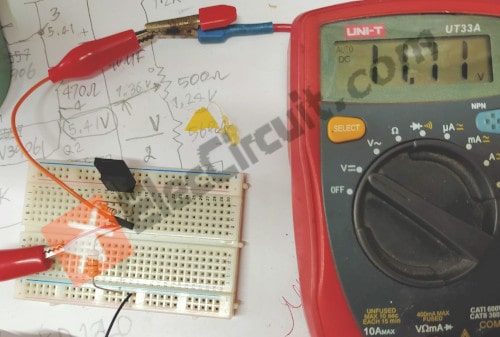
Then, I test it on the breadboard. They have similar values (11.72V). Thus, we can use this formula.
On the other hand, if we want the output voltage to be about 12V, what should the R2 value be?
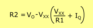
Or
R2 = (VO – 5V) ÷ {(5V÷R1) + IQ}
R2 = (12V – 5V) ÷ {(5V ÷ 120Ω) + 0.005A}
= 150Ω
Do you see a problem with this method?
We often do not have a resistor that we got from our calculation. It causes the output voltage to move away from the desired value.
Thus, we better replace R2 with a potentiometer.
Adjustable output voltage
We can adjust the output voltage from 5V to 24V via the R2-potentiometer connected to the GND.
Look:
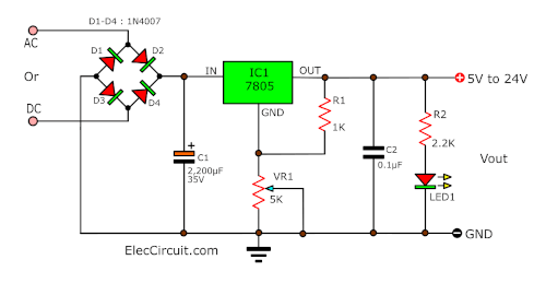
The input voltage and heatsinking of the regulator must be sufficient for the output voltage and current.
If the input voltage is 24V to 36V. The output may not deliver more than 100mA @ 5V. Because the regulator is overheating.
Recommended:
Let’s make 7805 Variable Voltage Regulator circuit
How to change L7805 voltage using diode
This is another way to increase 7805’s output voltage using diodes.
A diode is a common component in many stores. Such as 1N4148, 1N4007, etc. They have high efficiency and are suitable for general uses.
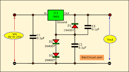
Circuit diagram of increasing output voltage 7805 using the diode
While the electric current is flowing a diode in forwarding bias. It has a voltage across that is very stable at 0.65V in each diode.
In the circuit above…
We add both diodes D2 and D3 (1N4148) in series between a common leg of IC1 and Ground. The output voltage will rise to 1.3V (0.65V + 0.65V) across both diodes.
Thus, the output of this circuit is 6.3V (1.3V + 5V)
Also, we add a diode D1 to protect the regulator from being damaged. It may have a feedback output voltage coming from a load. The D1 is connecting in the reverse bias, it will absorb the current spike to protect this circuit.
Next, we add 2 capacitors C1 and C3 to filter out the transient noise. Which can be induced into the regulator by stray magnetic fields.
In addition, adding a capacitor C2 across both diodes improves stability in regulation. It will reduce noise at the output.
See more: 6V power supply circuit diagram
High input voltage circuits
We know that we cannot use 7805 with an input voltage higher than 30V. These ideas below may be good to do.
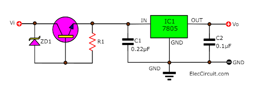
First, use a current limiting resistor. It is easy and cheap. But it will also reduce current down. Therefore, it is suitable for a low current load.
Next, by helping the transistor and Zener diode, this makes it can supply more current and steadier as well.
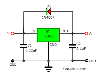
The Diode Protection
Although this IC has a very good protection system. But a reverse polarity voltage can still damage it. Therefore, we should put in a protective diode.
Output Polarity-Reversal-Protection
In many cases, a regulator powers a load that is not connected to the ground. But it is connected to a voltage source of opposite polarity (e.g., operational amplifiers, level-shifting circuits, etc.) instead.
We should connect a clamp diode to the regulator’s output, as below.
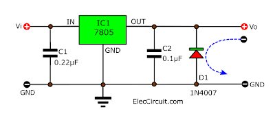
This protects the regulator from output polarity reversals during startup and in short-circuits operations, too.
Reverse-bias protection
Sometimes, the input voltage to the regulator might collapse faster than the output voltage.
This can occur. For example, when the input supply is Interrupted during an output overvoltage condition.
If the output voltage is greater than approximately 7V. The emitter-base junction of the series-pass element (internal or external) may break down and be damaged.
Use a shunt diode to prevent this, as in the circuit above.
High Current 7805 with transistor
If you require more than 1A of current. Then, combine LM7805 with other components to provide an output of up to 3A. As in the circuit below.
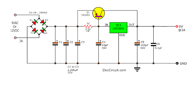
The TIP2955 transistor can accept the high current by itself. Thus, the LM7805 can run without a heatsink. It only regulates the voltage.
Note:
- Use the 3A diodes (1N5402) in the power supply. For currents greater than 3A.
- Use 3 x 2,200uF electrolytic capacitor in parallel. They have more capacitance are 6,600uF for 3A current filter.
3A Regulated Power supply with short circuit protection
In the previous circuit, when a short circuit the TIP2955 runs with a high current causing it to be too hot. Then, it might be damaged.
The easiest way to protect it is with a normal fuse.
We use a 3A fuse. When the current exceeds 3A, the fuse will blow immediately, is it easy? But if the fuse blows frequently, it can be inconvenient.
Next, use another PNP transistor (Q2) to check the error current.
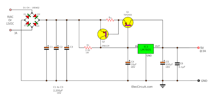
You can learn how to find R1 and RSC resistances, read more here:
Design: 12V 5A Power supply using LM7812 Although it uses 7812, I believe you can adapt it for other uses.
Positive and Negative Dual regulator
Sometimes, we need a +5V and -5V Dual power supply for Op-amp circuits, and more. We can use 7805 for making this power supply as below.
This design focus on economical and cost-effectiveness.
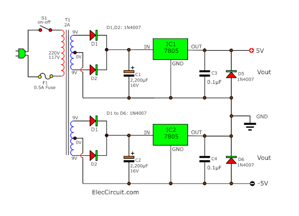
This circuit requires the 9V CT 9V 2A transformer, for the full load of 1.5A.
But if you do not have this transformer! Read recommended Dual power supply:
7805 and 7905 Dual adjustable power supply
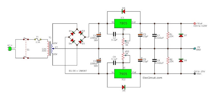
Do you try the OP-AMP Linear IC? They need to use positive and negative power supplies. For example, +15V Ground -15V. We can adjust the DC voltage from +5V to +25V and -5V to -25V at current 1A. Read more: 7805-7905 Dual Adjustable power supply
Constant Current using L7805
Imagine you want to charge a battery with a constant current and fixed voltage. You have many ways to do it.
But the interesting way is using L7805 as the current regulator circuit. Because it is easy and cheap.
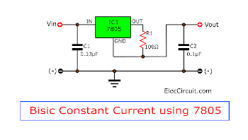
You can easily set the output current with the R1 resistor. Here is a current regulator calculator.
IO = (VO/R1) + IQ (bias current)
- IQ (bias current) = 5mA
What more? If you like this circuit. Let’s learn more: 7805 Constant current charger
Download This
All full-size images of THIS POST as PDF in the Ebook. Thanks, support me. 🙂
And more…
- Variable Regulator using 7805 and OP-AMP
- 5V 5A, 8A Power supply circuits
- 12V to 5V Step-Down Converter
- Fixed Voltage regulator using 78xx
GET UPDATE VIA EMAIL
I always try to make Electronics Learning Easy.
Related Posts

I love electronics. I have been learning about them through creating simple electronic circuits or small projects. And now I am also having my children do the same. Nevertheless, I hope you found the experiences we shared on this site useful and fulfilling.
What a Great Explanation of one of my favorite Integrated circuits ….the 7805 Regulator I built an interesting Power Supply using a LM350t ( 3a..Variable Regulator and a 7805…7808 and a 7812 regulator.I ran them through a rotary switch so I could select 5…8 or 12volts to power my Electronics Circuits!!Talk about over using a Regulator!!!
Good day
Yes, I also like LM350, 7805, and 7812 regulator ICs. But I do not use 7808 because no circuit requires 8V.
It is a great idea to use the rotary switches to select each IC for different output voltage.
Even, if it has a voltage across itself is high and lost power in heat. But I love linear regulator IC, It is easy and cheap.
Thanks
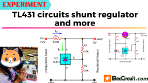
is it possible to get a variable Voltage supply From 1 to 5 volts conecting tata TL431 to the ground connection of the 7805 and connecting the reference Connectrd to a Voltage divider between the 7805 output and ground
Hi,
Thanks for your opinion, I and my dad have tried this circuit https://www.eleccircuit.com/0-12v-variable-power-supply-at-3a/, it might be able to be applied to your needs.
It is possible that if we apply negative voltage to GND, the output voltage will be offset and default to 0-5V. It’s an interesting idea. Dad and I might try it out. Thank you for your idea. Hope you will follow us again. 🙂