My children and I have been using the LM350 regulator IC with its high current throughput and low noise-to-current ratio. However, it can only supply a minimum voltage of 1.25V, which might be problematic when we need a voltage below 1.25V.
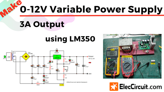
So today we are going to find out how to lower that minimum threshold to 0V by making a 0-12V 3A Variable Power Supply using LM350.
Note: if you are a beginner, I recommend learning the basics of the LM350 regulator circuit first, it will help you better understand it.
How to
We found that there are two ways of achieving it, namely:
- Two diodes in a series
- Apply negative voltage at Adj
Two diodes in a series
Through the property of a common silicon diode, we know that its forward threshold voltage is around 0.7V, meaning that the voltage below this threshold could not pass at all.
It can also be increased by connecting a pair of them together in a series. Giving us a threshold voltage of 1.4V (in practice, around 1.36V), which is higher than 1.25V, preventing a current from flowing through. Therefore, the output voltage will be zero.

To better understand, we can compare it to a weir slowing the water down.
Suppose that this weir has a height of 1.36 meters, but the water level is only 1.25 meters high. The water would not be able to flow over it to the other side. But when the water level increases to 1.37 meters, which is 0.01 meters higher than the weir itself, a delta of 0.01 meters flows over.
Using diodes in this way is both easier and cheaper, but you should choose a diode that can withstand high currents.
In this case, we chose two 1N5402 diodes as they can withstand up to around 3A of current, which is sufficient for this usage.
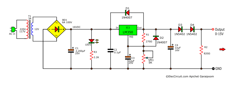
Now we put it to work, as shown in the circuit below.
You will see that it looks similar to this circuit.
But with a notable addition is R2, which acts as a bleeder resistor, discharging the current of C4. Apart from this, it also improves the reliability of the circuit when there is a low load current.
And it only pulls 10mA of current at the maximum output voltage.
However, there is a downside to this way of doing it. Similar to a resistor in series, it will definitely hinder the current flowing to the load.
Parts list
T1: 12V to 15V @3A primary transformer, Quantity:1.
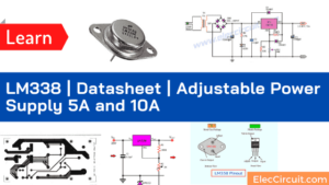
IC1: LM350T, 3A Regulator , Quantity:1.
BD1: 6A to 10A Diode bridge, Quantity:1.
R1: 270Ω 0.25W , Quantity:1.
R2: 820Ω 0.5W , Quantity:1.
R3: 2.2K 0.25W , Quantity:1.
VR1: 5K Potentiometer, Quantity:1.
D1,D2: 1N4007 – 1A 1,000V – general purpose Diodes, Quantity:2.
D3,D4: 1N5402 – 3A 100V- Diodes, Quantity:2.
LED1: 3mm Red LED
C1: 2,200µF to 4,700µF 25V Electrolytic capacitor, Quantity:1
C3,C4: 22µF 25V Electrolytic capacitor, Quantity:2
C2: 0.1µF 50V Ceramic or Mylar capacitor, Quantity:1
Be careful! Look LM350 pinout:
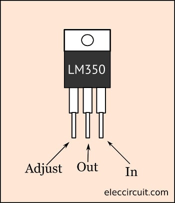
Some may not know.
Apply negative voltage at Adj
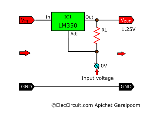
When we apply a 0V control voltage to the Adj pin of the LM350, the Vout will always be 1.25V.
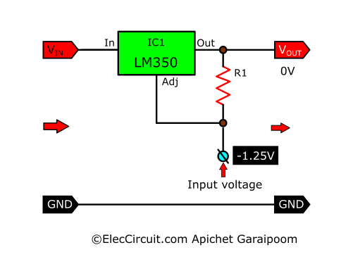
This voltage can be achieved with two diodes as well, as shown in the illustration below. A negative 12V Vin flows through R2, reducing its current to power D3 and D4, causing their voltage drop across to be a stable -1.4V, which is close to what we need.
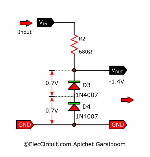
But it is still higher than we need. So if we apply them to Adj, the output voltage will turn negative around -0.15V.
We can mitigate this problem by adding a resistor in series with the VR1. That resistor will add voltage, making the output positive.
At last, through our trial and error, the resulting complete circuit works quite well.
Recommended:

It is similar to the above circuit but with a couple of notable exceptions, including:
- Change the transformer to the one with 12V CT 12V secondary coil, so that it can supply a negative DC voltage while still keeping the same BD1.
- Add C2 and C3 to smooth out the current; this also protects against ripple voltages.
- Add a negative DC power supply circuit, which consists of C7, R3, D3, and D4. C7 value at 470uF since the Adj requires very little current.
- Add R4, 27ohms, to offset the minimum output voltage to 0V.
Want more brilliant ideas? Here’s how to get them through electronic circuits.
Parts list
This circuit has an electronic components list that doesn’t include too many; you can find it anywhere.
T1: 12V to 15V CT @3A primary transformer, Quantity:1.
IC1: LM350T, 3A Regulator , Quantity:1.
BD1: 4A to 10A Diode bridge, Quantity:1.
R1: 270Ω 0.25W , Quantity:1.
R2: 2.2K 0.25W , Quantity:1.
R3: 680Ω 0.5W , Quantity:1.
R3: 27Ω 0.25W , Quantity:1.
VR1: 5K Potentiometer, Quantity:1.
D1 to D4: 1N4007, 1A 1,000V – Silicon Diodes, Quantity:4.
LED1: 3mm Red LED
C1 to C3: 2,200µF 25V Electrolytic capacitor, Quantity:3
C4: 22µF 25V Electrolytic capacitor, Quantity:1
C5: 47µF 25V Electrolytic capacitor, Quantity:1
C6: 0.01µF 50V Ceramic or Mylar capacitor, Quantity:1
C7: 470µF 25V Electrolytic capacitor, Quantity:1
Do you want a -0V to -12V variable Regulator circuit, Look at this idea: 0-60V Dual Variable power supply circuit using LM317&LM337
How to builds
We decided to assemble this circuit on a perforated PCB because of how few components it has. After that, let’s start fine-tuning by setting the voltage to a minimum of 0V. If the voltage falls below negative, you might want to up the R4 resistance to 33 ohms or more until it reaches 0V.
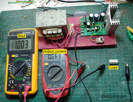
Then set the voltage to 1V and use a 1ohms 5W resistor as a test load. We will see that the voltage drops a bit and the current reads out at 0.66A. The heatsink should also be warm to the touch, showing that the circuit functions properly.
Note: The ammeter of the resistor used in testing might have small inconsistencies. Apart from this, the LM350 might have also supplied low current during a low voltage range.
Conclusion
Through our experimentation today, we found that it’s possible to lower the minimum output voltage of the LM350 with these two methods. The first method is the easiest, but the efficiency is quite low as the current drops. But the second method mitigates this issue by applying a voltage to the Adj pin and offseting the Vout until it reaches 0V instead.
Hope you can do it.
Also the 0-12V Variable power supply
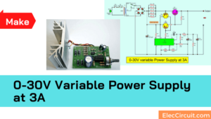
0-30V Variable Power Supply at 3A
GET UPDATE VIA EMAIL
I always try to make Electronics Learning Easy.
Related Posts

I love electronics. I have been learning about them through creating simple electronic circuits or small projects. And now I am also having my children do the same. Nevertheless, I hope you found the experiences we shared on this site useful and fulfilling.
How to add voltmeter to this circuit? voltmeter has three wires red, black and yellow?
Can I replace the potentiometer with 10K value?
Hi Ali Mohammed,
Thank you again.
How to add voltmeter.
Did you see this: https://www.eleccircuit.com/diy-digital-voltmeter-panel-meter-0-50v/
Yes, you can use 10K potentiometer. But you may adjust hard the output voltage.
You should add a 1K resistor in parallel with it. Both resistance mix together into about 1K.
I hope you will understand me said.
Have a good day.
Is this working?
I’ve tried it and it doesn’t work.
Hi,
Sound bad, this does not run.
I did not want to see you are disappointed.
Please continued to check it again.
See text.
Should i use the 2 12v terminals of the transformer or the 12 and 0 terminals?
Hi Yo matam,
You may use 12V OV terminal. Use bridge diodes are better than Full-wave rectifier. Keep reading more: https://www.eleccircuit.com/unregulator-power-supply/
Hello,
Hello, I made the 0-12 V DC power supply and 3A current with the LM 350 circuit, but with a 1K potentiometer, the voltage adjustment goes from 0 to 6.65 volts. (no load) I tried another 6.8 K potentiometer and the adjustment went from 0-13,5 Volt. (no load) without diodes Diodes D3 and D4 because they completely block the output voltage. Please, how should I act for diodes D3 and D4? I am waiting for your response. With respect Ilir
Hello,
Thank you for visiting your website. My Dad and I are very sorry that this circuit was faulty. We accept this mistake now. We have tested this circuit well. It worked as we expected. That this experience will be beneficial for you to use this circuit again better than before. And sincerely hope that you will continue to follow our work. 🙂
Hello,
I want to know if it’s possible to utilize the -12v terminal for a 0-(-12v) output along with the existing 0-12 output, but keeping the -1.25v modification and adding a +1.25v modification for the negative side. If yes, would you give me a hint on how to achieve that.
Thanks, and I hope you’re having great days.
Hi,
Thanks for your visiting. I like your asking. Please check this: https://www.eleccircuit.com/0-60-volt-dc-variable-power-supply-using-lm317lm337/
You may use this circuit idea, we believe it might solve your problem. We regret that we were not good enough at explaining this in the text. And we’re busy testing the circuit to solve the problem for you right now.
But we believe You can definitely do it. Have a great day. 🙂