Why use the 78xx voltage regulator? When our electronic projects require a fixed regulated DC power supply circuit. For long times ago. I often use a Zener diode and transistor to build a regulator.
They are good but have many parts. So, now the first choice, we recommend using IC (the integrated circuit in the 78xx family).
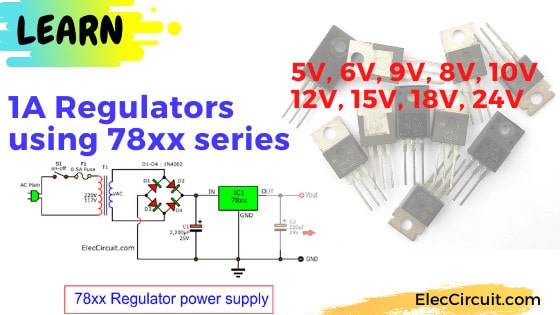
They can be a fixed regulated power supply source. They give output voltage: 5V, 6V, 9V, 10V, 12V, 15V, 18V, 24V at 1.5A max current. It is easy to use, cheap, popular for a long time.
Parts used in this below circuits are easily available in most of the local markets.
For example circuits, use 78xx series in fixed positive voltage regualtors.
Suppose you are a beginner. All things in Electronics is too confusing. But you are interested in learning it. I used to be like you. I love learning through the circuit. When I watch a lot of circuits. I started to understand its system.
I try to design(draw) 9 example circuits for you. I hope you are clear with these circuits.
Recommended: Learn how series circuit works
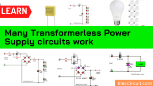
78xx Power Supply circuits
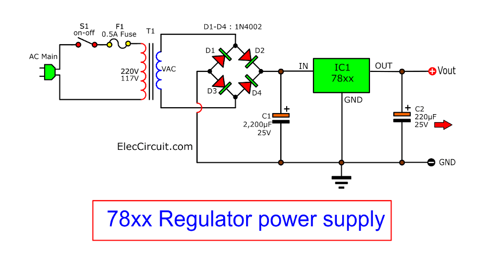
We use voltage regulator IC-78XX series Or some call 7800 series. You can change Voltage output get follow want IC number!
- 5V uses IC-7805 Voltage Regulator circuit,
- 6V uses IC-7806
- 8V uses IC-7808
- 9V uses IC-7809
- 10V uses IC-7810
- 12V uses IC-7812
- 15V uses IC-7815
- 18V uses IC-7818
- 24V uses IC-7824
The load is typically regulated to within 10mV and no more than 50mV.
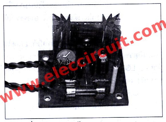
We still use PCB and other equipment as before. To use transformer 1-2A. IC-7800 series to Hold Heatsink.
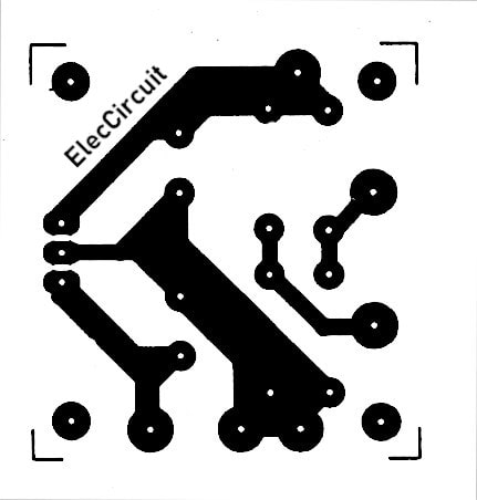
The copper PCB layout
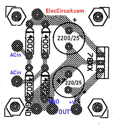
The components layout
5V Regulators using 7805
9V to 5V DC Converter Circuit
This is 5V portable power supply circuit for pic microcontroller experiments.
or PIC microcontroller power supply circuit.
As The PIC16F627A microcontroller use 5 volts DC power supply. My son need to build it as 5V portable power supply circuit, because of the need for safe and convenient use in all locations.
How it works
I want my son to embarked on building this projects by himself. So choose a simple circuit. as Figure 1. We use IC-7805 5 voltage DC regulator IC, which has been very popular.
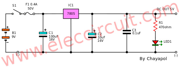
We use the power supply input is 6 x 1.5V AA battery, Are connected in series The total voltage 9V. We used a conventional battery. It’s easy and cheap to buy.
Parts will you need
S1: switch to turn on-off this circuit.
F1: Fuse is used to protecting this circuit from overload output. We use 0.4A 50V only to safe all circuit.
IC1: convert an input voltage from 9V to 5V and the ability to maintain the regulated supply
LED1: for show power on
R1-resistor: reduce current flow to LED1 in safe value
C-100uF 16V-Electrolytic Capacitors: to filter current to smooth
C-10uF 16V-Electrolytic Capacitors: to filter output current to smooth
C-0.1uF 50V-Ceramic Capacitor: to reduce noise as ripple voltage on a high spike
Then I tech my son understand all components using on this project. As Figure 2 he draws them on his notebook.
Figure 2 all components that we use
How to builds
Next step He solder parts on DIY Prototype Paper PCB Universal Board as Figure 3
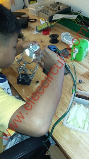
Figure 3 To solder parts on DIY Prototype Paper PCB Universal Board
We use a small nail clipper To amputate those devices Because it’s small, easy to use And very cheap as in figure 4
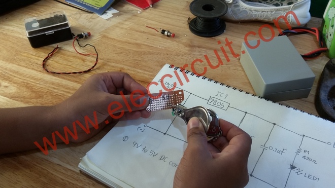
Figure 4 pins cutting with nail clippers
Then, we apply 9V power supply to the circuit, and measure voltage output is 4.95V it is ok.
Next, I assemble the circuit in the Box as Figure 5, it look is great, this step I help my son build it because it is hard for him.
He draw text on the box to clear to use.
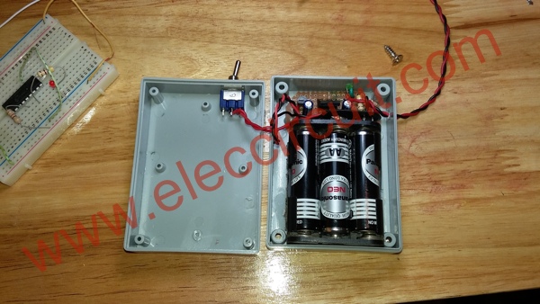
Figure 5 assemble the circuit on the box
Then, We test with the PIC16F627A circuit pic microcontroller experiments as Figure 6 it works well.
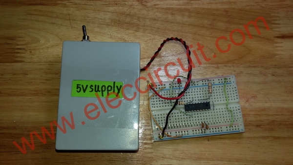
Figure 6 test this projects with PIC16F627A circuit.
The parts we will need
IC1: IC-7805 5V DC regulator
C: 100uF 16V __Electrolytic capacitors
C: 10uF 16V___Electrolytic capacitors
C: 0.1uF 50V___Ceramic capacitors
LED1: LED as we like
R1: 470ohms 0.5W resistors
S1: ON-OFF switch
F1: Fuse 0.4A 50V
The Box, Wires, PCB, and more
Portable MP3 player Supply
This is a USB motorcycle power supply circuit. Motorbike repairman came to my house. Said, you know the story of how I like to build various electronics projects are always. And Talk to exchange knowledge with each other.
During this time, he had been installed the stereo in a motorcycle. Can turn to music Sound of reasonably good.
The regular budget, $ 50, depending on the speaker. (The bass -treble as you like) And small amplifier but high power (around 50 watts)
The source of music. He chose a portable MP3 player. Since there are several advantages as follows:
– small, easy to install.
– Battery built-in so not require an external power supply. When power is applied to charge it with the home AC power.
– Withstand vibration better
– Music store has hundreds of songs or more.
– To listen to FM radio.
Typically, he allows customers to buy into it. Since there are many to choose price under 20 $.
However, using this a portable MP3 player (an example Figure 1) It is not easy, because the battery runs out of power fast. Listening to music is not long or discontinuous, it must be removed to renew to charged.
Figure 1 The portable MP3 player

He had the idea to adapt draw power from the battery of the motorcycle used as a power supply of this portable MP3 player instead.
Based on such a problem, I see that is interesting so Thus volunteered to help him, by Appropriate focus on quality, ease of build. and saving budget (lower than 20$)
Figure out a way to match
He has further commented that the battery provide voltage of 12-volts. But this MP3 player use 5-volts power supply so must to have to the device to reduce voltage to 5-volts fixed. Because too much voltage may damage or permanently destroy the semiconductor chip in this MP3 player.
The current use he not tell me but I think do not many current because it use small LCD display and use one 1.5V battery only.
I think that the good device reduce voltage, is a steady 5V regulated power supply there. In In mind that use IC-7805 pay fixed voltage 5V 1A, Thus try to think of ways to make the design work, as Figure 2 appear to be more effective available.
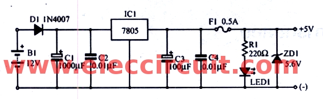
Figure 2 the 12VDC to 5VDC regulator circuit using IC-7805
The working principle.
We try to understand the circuit better. When connented the battery the current will flow through D1-diode by it serves to protect the connecting wrong polarity,is allow the positive only.
Also, while the 12-volts battery very weak, may be noise mix with voltage battery. But when has D1 will has new rectifier on positive voltage only that can get with them.
Then the current flow to C1. Which serves as filter to smooth. And The C2-capacitors acts reduce high noise frequency.
Then the input of IC1 and supply voltage of 5V regulated at output. By has C3 to filter voltage to smooth and has C4 reduce noise other on level.
Although IC1 would then overcurrent protection. But as a precaution. I insert F1-fuse protect over current of 0.5 A.
And I added ZD1 to protect over voltage., If the voltage exceeds 5.6V. Would be current flow through ZD1 lot. Makes F1 lacking in the end.
For LED1 to show the performance of circuit., If a 5-volts LED1 will light up. Except F1 lack or no power input. The R1-resistors connect to limited current of LED1 perfectly.
How to build
For the prototype. I assembled two sets him, both on the universal PCB board and on PCB as Figure 3 is Actual-size of Single-sided Copper PCB layout and has components layout as Figure 4 same generally projects.
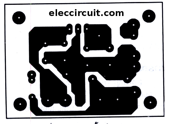
Actual-size of Single-sided Copper PCB layout.
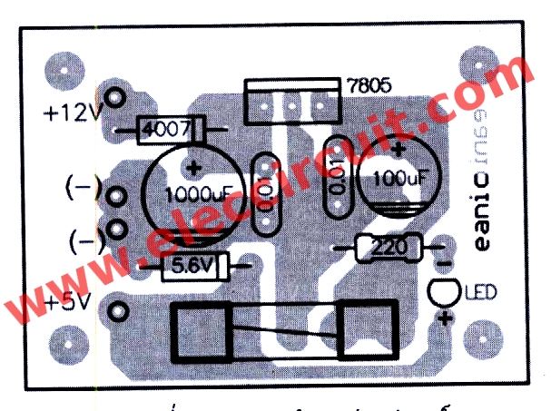
Components layout
Prototype-based on this project
You should wiring and components for errors. Rub pin devices, to help soldering easier, and leg positioning device correctly. In particular the electrolytic capacitors and diode.
Also, proper soldering with a soldering iron, no larger than 30 watts and use the lead for good.
Until success is a prototype based on Figure 5.
Application
When soldering equipment and review their completed successfully. To take the 12-volts battery to enter in this circuit will see that LED show power on is indicated circuit works so well.
Then, try to take the portable MP3 player to the Motorbike as Figure 6 It turns out that a good result he let the fire is not left open several hours before this circuit that actually works. No problem
The parts you will need.
IC1: 7805 DC voltage regulator
D1: Diode 1N4007
ZD1: Zener diode 1N4007
LED1: LED as you need
C1: 1000uF 25V Electrolytic
C2, C4: 0.01uF 100V Mylar capacitors
C3: 100uF 25V Electrolyte
R1: 220 ohm 10K 0.25W -5%
Heat-sink 1 pcs.
PCB 1 pcs.
Keep reading: ‘7805 5V voltage regulator’ »
7806 DC Regulator 6V
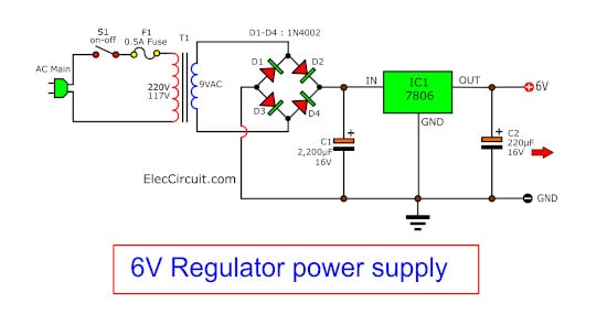
The main parts of this circuit IC 7806. It is normal IC linear dc voltage regulator 6V at 1A current.
It is easy project electronic because used the minority part and low cost too.
I have of a 9Vac 1A transformer. The output of the transformer is rectified by diode 1N4001 or equivalent to more high power,
Thence to smoothed filter using 470uF 35V capacitors,so the volt this is unregulated DC voltage have value 11V-12V DC.
Besides must use this ic with a suitable heatsink.
Detail more, Please in image circuit.
8V 1A Regulator using 7808
If you want DC regulator 8V for your camera that use current about 800mA.
I recommend you try to use L7808 or LM7808 in TO-220.
Look at the photo below.
It is similar to other ICs in the 78xx series. The output current is 1A max and easy to use.
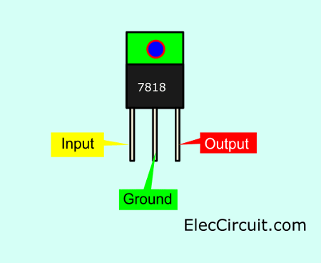
And Look 7808 Pinout here.
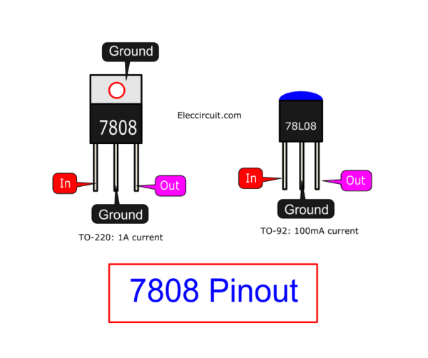
Feature
- The input voltage min 10VDC to 30V Max.
- Line Regulation: 0.25%
- Load Regulation: 0.25%
See in the circuit diagram below.
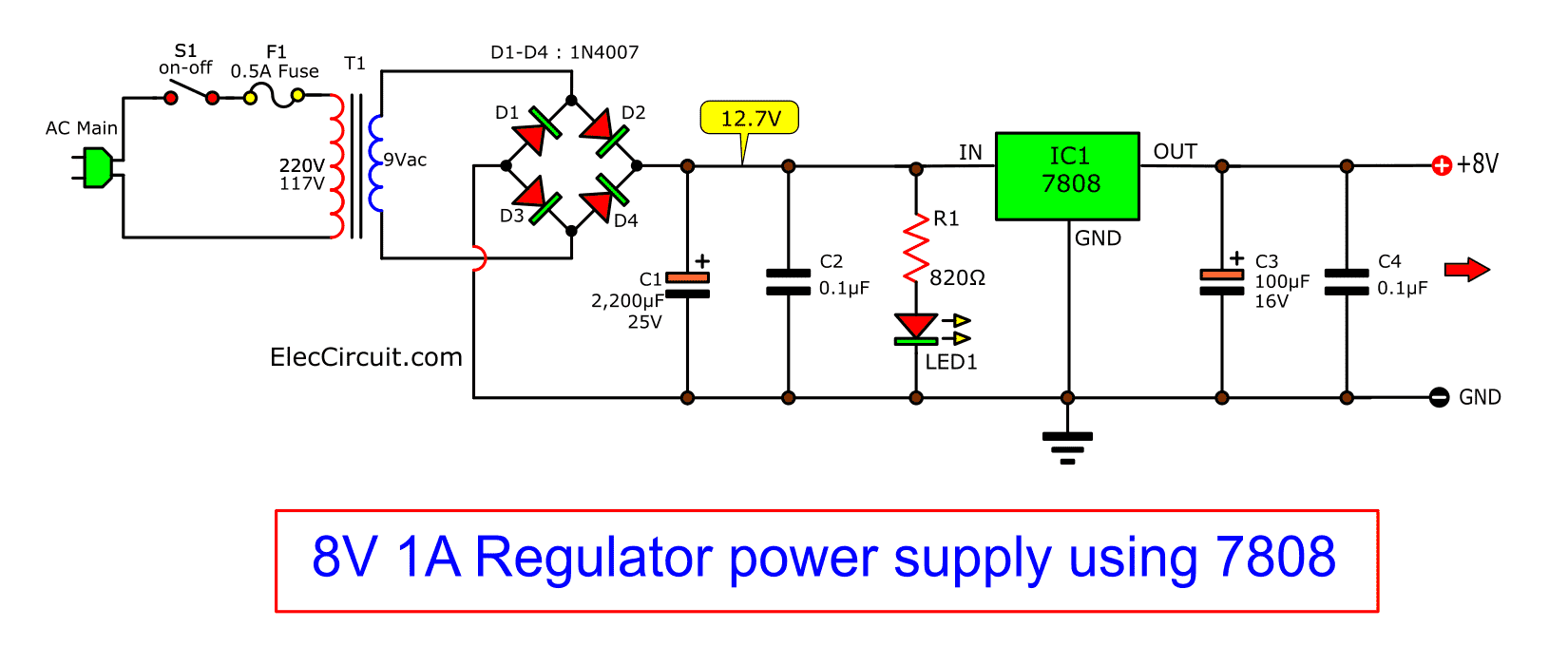
Here is 8V DC Regulated power supply circuit.
Max 1A.
You should install enough heatsink to it.
18V power supply circuit diagram
When we need to build an 18V DC power supply circuit. For a transistor pre tone control. It will have a quality sound. If we use a stable DC voltage regulator.
We have many circuits to build. But now we like the 18V DC power supply circuit using IC-7818. Because it is so well circuit, small in size so fast to build, sometimes we can assemble them on a breadboard. And cheap we like it!
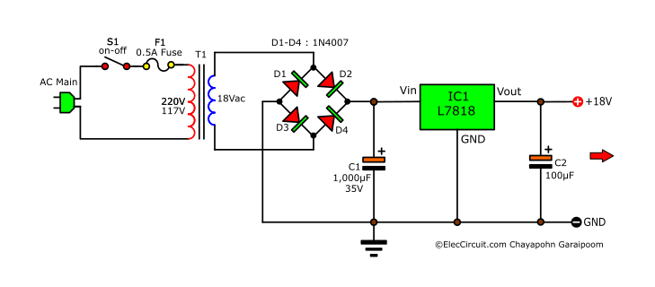
The 18V DC power supply circuit
The IC-7818 or LM7818 or L7818 is a circuit’s key. It is a fixed DC voltage regulator IC that so popular. Since they have a low load regulation so low noise signal on our audio system.
The working principle
As we build this circuit put on the power amplifier. So The output terminal of the transformer is our AC voltage input. The proper AC input range from 18V to 22V.
You may use the 18VAC 1A transformer. It makes an output current of 1A.
Then, the AC voltage passes through a full-wave bridge rectifier (D1 through D4). They will rectify the AC into pulsating DC.
Next, the 1,000uF 35V- capacitor will filter a pulsating DC into the DC unregulated voltage. Which this voltage about 24V to 26V.
If the output current is not full to 1A. You may add one 1000uF 35V capacitor. It can keep more current.
This DC voltage will flow through the input of 3-terminal IC1. It will converter any DC voltage to stable +18 volts regulated.
The 470 uF 35V capacitor filter DC voltage to smooth better.
Now, we have the stable regulator of 18V DC power supply for a lot of application next times.
Although the IC has good circuit protection. We have to use the IC1 with a suitable heatsink because while it is working with the high current it so heats.
Parts list we need it
IC1: LM7818 or L7818_18V voltage regulator
C1: 1000uF 35V_Electrolytic Capacitors
C2: 470uF 35V_Electrolytic Capacitors
D1: D4: 1N4007_1000V 1A Silicon Diode
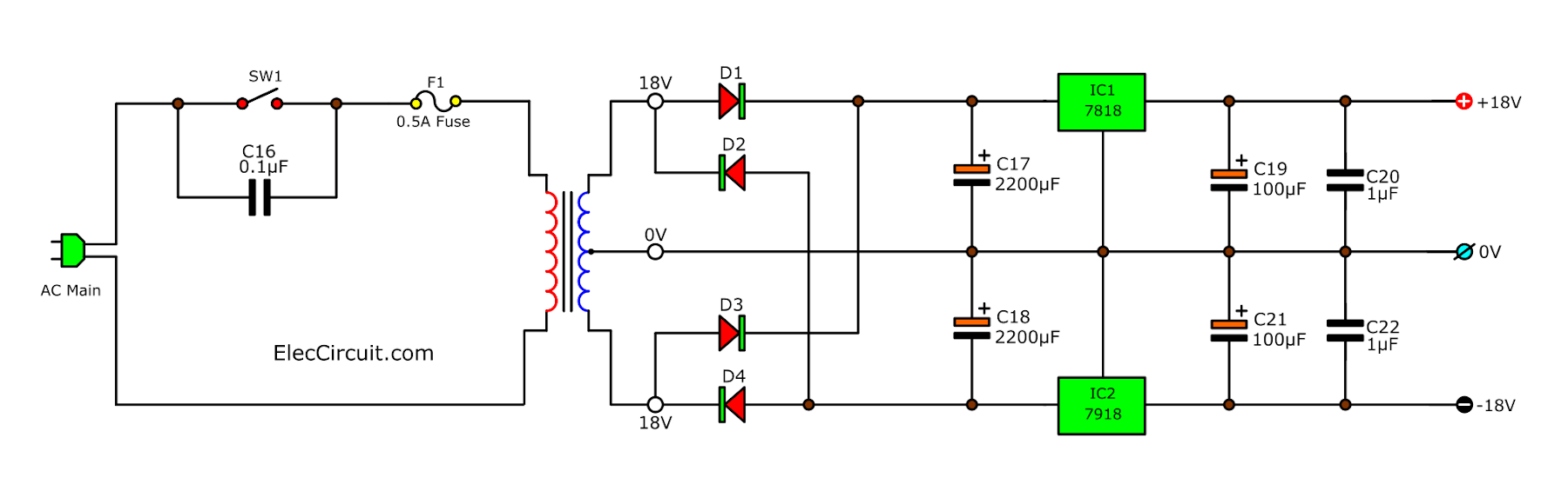
18V Dual DC Regulator circuit
Some circuit requires an 18V dual power supply circuit or 3 terminal output (+18V, – 18V, and Ground).
We can use IC7818 and IC7918 to do this power supply.
 Also, see
GET UPDATE VIA EMAIL
I always try to make Electronics Learning Easy.
Related Posts

I love electronics. I have been learning about them through creating simple electronic circuits or small projects. And now I am also having my children do the same. Nevertheless, I hope you found the experiences we shared on this site useful and fulfilling.
5-volts DC regulator for portable MP3 player on motorbike….
the zenner diode should be a BZ5.6 and not a 1N4007 as stated, lol
Paul
hello sir!
can you give me a diagram on how I could extract 12v dc from a motorcycle rectifier that outs 14v at less than 1k rpm and shoots up to 20v when at high rpm. It boils my battery and after a month breaking it. its really expensive to buy a battery hoping you could help me on this
#18V DC power supply circuit using LM7818
building a wind mill gen gets 2vd to 28vdc can I make a unit to get a good steady rate of 16vdc up to 10amps no one can see this possible ???
Dear sir, my solar regulator is working properly it drain power voltage in battery ,what can i do with it?
design 12vregulated power supply using ic 78xxseries and calculate % of load and line regulations
Dear sir, i need to rectify the CT output current
and to convert current to voltage to read from micro controller, so what can i do.
please include the design factor,terms & equations of 5V power supply using 7805IC
#18V DC power supply circuit using LM7818
I see your 18v power supply circuit. I think you forget about the voltage drop here. coz when u take 18 v AC Transformer it gvs 18 v but what about ic and diode voltage drop and conducting voltage.?pls explain
Hi, i want create your “Power Supply 5V 1A by IC 7805” but using an DC input of 24V/10A, is this possible? and if it’s possible, could you tell me what to change in your circuit!
I’m a newbies with electronics, be indulgent.
Nice Project You have Here!!!! This would Be Handy If You were Using TTL IC’s to be powered from this Power Supply Because These IC’s Require a stable 5 Volts.Awesome Post..Many Thanks From MR.OHM1970
Hi, i want create your “Power Supply 12vdc/1A by IC 7812″ but using an DC variable input of 12vdc to 24vdc, is this possible? and if it’s possible, could you tell me what to change in your circuit!
I’m a newbies with electronics, be indulgent.
Sir I need a ckt diagram of 6v dc power supply and output current max 250 mAmp using transistor
Sir I try this but working. If I connect the mobile so the battery of the mobile is going low and the power bank is charged.
I made a 9volt battery to 5 volt phone usb charger using ic 7805, but my phone samsung glaxy grand prime did not shows charging (2600mAh) battery.
But same circuit when i use to plug with other phone having 2300 to 2400mAh battery it shows charging.
Should i use other regulator like 7806 or any other.
Can any body help me?
Amigo (a); como para que tipo de aparato lo quieres ??? me imagino que hizo una fuente sencilla normalmente, estos aparato consumen una corriente de carga de flotación a plena carga máxima aproximadamente 1200 ma /5.7 volts por lo resta tiene que estar estable sino se hace muy inestable la batería y, puede explotar la misma batería.
Hi Arsalan,
Thanks for your visit to my website.
I did not understand you say to me. What did you meaning?
It is not important. I will try to answer you. You are the importance.
Did you need a DC power supply, 5.7V 2A up?
You will use it instead of a 5.7V battery.
I have many Ideas.
1. https://www.eleccircuit.com/lm350-adjustable-voltage-regulator/ Cheapest and easy!
2. https://www.eleccircuit.com/cheap-adjustable-0-30v-3a-laboratory-dc-power-supply/ Good Circuit!
3. https://www.eleccircuit.com/best-dc-power-supply-3amp-to-adjust-1-2v-20v-3v-6v-9v-12v/ It is old circuit but I like it.
I hope you are happy with your circuit.
Thanks
sir can i use ic 7812 in parralel to increase out put amper?
Hello sir,
I m making a project of low battry indicator but this is operated with 12v dc and indicator is glow of less then voltage of 5v DC.
How i can change of this range 5v to 10v glow the indicator please suggest me.
Sir im useaing the ic for regulator for the cct is ic 7805.
Sir. I am using a wireless camera on my UGV..It is provided with an 9v 500 ma adapter.but I want to run it on a battery as.my UGV cannot accommodate a ac supply.so plz provide me with proper material list and diagrams.i shall be really thankfully
#5-volts DC regulator for portable MP3 player on motorbike
BZ5.6v zener does to work. mine allows me to go over ths. i also tried a 5.10v zener still same effect. it is connected correctly too
diode
plz sir I need a circuit diagram or rather PDF of 10volts power supply
Sir i am search about above 12v to 25v regulator ic’s with wireless circuit
I am search in the 5v output regulator
Such good service i want to 6 v dc to 3,6,9,12,24,v dc with 1 to 20 Ah suply with regulater with digital display howe much cost price pleas is available this product please tell me sir
Hi
Seeing all the post here, I think I might be helped here, I just need to make a 2.1 Computer speaker portable( got every component into one separate cabinet) it has 230v ac to 10-0-10v, 0.74 amp, transformer, I need running either on 5v power bank which I have or sealed 12v battery. Thank you in advance
Good day sir! You have a great work!
I would like to ask your idea on how to make a mobile charger that has an output of 5 volts 2 amperes.
Thank you sir.
Good day sir! You have a great work!
I would like to ask your idea on how to make a mobile charger that has an output of 5 volts 2 amperes from 12 volts battery.
Thank you sir.