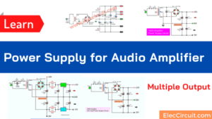
These are 15v dual power supply circuits for a preamplifier. If you finished a Preamplifier with tone control using op-amp completely. But they need a three-terminal power supply, +15V, OV, -15V at 0.5A current.
So, you have to build a 15V Dual Rail power supply schematic with PCB. I am going to show you 3 circuit ideas for you to choose as necessary work.
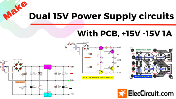
Dual 15V Power supply Schematic, 1A with IC-7815, IC-7915
Now, most people normally use IC-7815 & 7915 to this. Why use them?
- Cheap—they are in the 78xx and 79xx series. So cheap!
- Easy to use and Small—with 3 terminal pins input, ground, and output only.
- Great quality—the voltage regulator IC can keep the constant voltage at output and overload protection
How this Circuit Works
See in the circuit below.
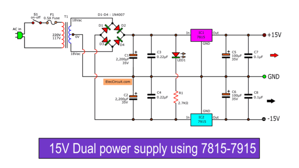
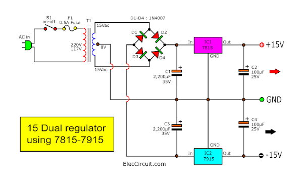
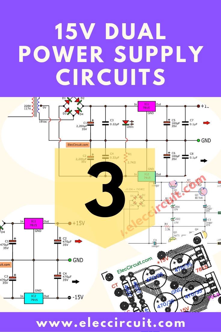
15V Dual power supply circuit diagram using 7815-7915
To begin with, the transformer should have a primary rating of 240V/220V for Europe or 120V for North America. The center tapped secondary coil should be rated about 15V to 18V at 1 A or higher.
This 15V Dual rail output power supply is powered by the transformer. The 220V AC mains comes to the primary. Then, providing into 3 rail voltage, 15VAC, 15VAC and 0V of the secondary.
After that, the current flows through a full-wave bridge rectifier. Which they consist of four 1A diodes with a 100 PIV rating. And then, the electrical current flow to both C1, C2 – 2,200 uF/35V capacitors to completely filter to providing the dual rail, +21VDC, OV, -21VDC.
The C3, C4- 0.22uF capacitors are used to filter noise signal in DC voltage.
Then, DC voltage comes to Both DC Voltage Regulator IC.
- LM7815 keeps the 15V positive voltage output.
- LM7915 controls -15V fixed negative voltage output.
Each IC can give a maximum output current of about 1A.
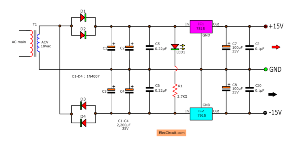
For more Capacitors C5, C6, C7, C8 are used to smooth and clean noise in DC output.
LED1 is power on display with R1 limit current.
Other detail both of the circuit.
How to build it
This circuit is easy. First of all, you should get the parts list.
The components list
IC1: LM7815, Positive Regulator 15V 1A = 1 pcs.
IC2: LM7915, Negative Regulator 15V 1A = 1pcs.
D1-D4: 1N4007, 1A 1000V Silicon Diodes = 4 pcs.
C3, C4: 0.22uF 50V, Ceramic Capacitors = 2 pcs.
C7, C8: 0.1uF 50V, Ceramic Capacitors = 2 pcs.
C1, C2: 2,200uF 35V, Electrolytic Capacitors = 2 pcs.
C5, C6: 100uF 25V, Electrolytic Capacitors = 2 pcs.
R1: 2.7K 1W Resistor 5% tolerances = 1 pcs.
LED1: LED as you like = 1 pcs.
T1: Transformer 15V CT 15V or 18V CT 18V 1A to 1A = 1 pcs.
Then, assemble on perforated board or Universal PCB board. as the image below.
And can see a video testing circuit.
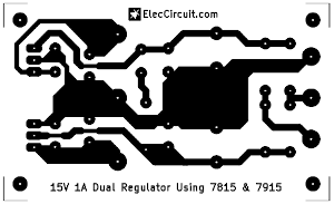
However, if you need to build a PCB, you can see the PCB layout and components layout below.
15V 1A Dual Regulator using 7815&7915
Some times we can make it easily with removing some components. It is save, too.
Look a smaller circuit below.
This circuit is suitable for…
- Load uses a little current like a preamplifier circuit.
- Have filter capacitors within the load circuit already.
- For little installation space.
- A few components sometimes you hurry up.
Difference
- Change the size of the transformer to 0.5A or 1A max
- Remove 0.22uF capacitors because in load use low current low noise. It may be added later (you want).
Also, you can build it easily with PCB layout below.
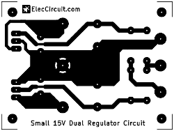
Here is Actual-size of PCB layout of 15V Dual power supply using 7815-7915.
If you make PCB with yourself. You should print it on 300dpi.
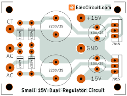
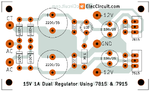
And the component layout.
An application for this type of circuit. It is suitable to be a small regulated bench power supply. Also, you look at second ideas.
Recommended: Do you want a 12V Dual Regulator circuit to experiment with the OP-AMP circuits?
Using 2 terminal transformer
My friend (Mr. S.Kathiravan) wanted to use this circuit with a 2 terminal transformer. It’s very interesting. I like this concept.
Look at the circuit idea
In the principle of an Unregulated power supply, we can use a half-wave rectifier, but it will have lower efficiency (more ripple).
- A double filter capacitor is more capacitance to smooth current.
- Diodes take more energy. So we should add two more in parallel to get higher the current.
15V Dual Power supply circuit For Preamplifiers
In the previous circuit, use a regulator IC. I want to show you another way to build 15v dual power supply circuit for preamplifiers. It also can give a dual-rail output +15V, OV, -15V and maximum current output up to about 1A.
This uses a Zener diode and transistors. So easy to find parts and build easily it. Though very ancient, it still has many uses. Because it is a classic and low noise circuit. So it can power to a general preamplifier or pre tone control using op-amp or transistor.
How it works
This is a Schematic Diagram of Dual DC Regulator 15V using transistor and Zener diode
In the circuit below.
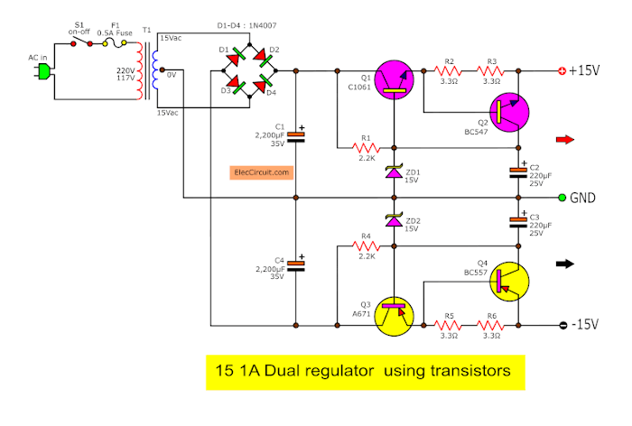
It is similar to the previous circuit. They consist of T1, D1, D2, D3, D4, C1, and C2. These components are the Unregulated supply section.
- T1—step-down transformer from 220V AC on the primary, and then providing about 18VAC + 18VAC on the secondary
- D1 to D4—full-wave rectifier bridge to convert AC to pulsating voltage DC.
- C1,C2—filter capacitors to smooth DC to a stable DC voltage.
Now, they get +24VDC, OV, -24VDC.
Then, the current comes to a filtering regulator section. They made up of R1,R2,R3,R4,R5,ZD1,ZD2,and Q1,Q2,Q3,Q4.
In positive regulator section(up). the current flows through R1 and ZD1. The Zener Diode keeps the voltage constant across the base of Q1. It is in a common collector. So the voltage of the base equals the voltage of emitter(VE). C4 is filtered any noise it +15V rail.
Recommended: Zener Diode Principle working, example circuits usage
So, the output is fixed voltage about 15V.
For negative regulator section is similar to positive (different polarity only). They include R2, ZD2, Q3, and C3. So they make -15V fixed voltage output.
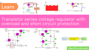
This has overcurrent protection with Q2 and Q4 transistors. When a load uses too much current about 1A, both positive and negative rail supply.
Makes a voltage across B-E of Q2, Q4 is high enough to turn on Q2 and Q4 work. When they work, its C-E leg like to be switch on to closes Q1 and Q3 stop.
Thus the output is zero current.
Let’s build 15V transistor Dual supply
At below, here is the PCB layout to guidelines to builds this circuit. Hope you fun Dual DC Regulator 15V using TIP41 and TIP42.
You can use others transistors. If you cannot get power transistors.
- 2SC1061: TIP41, TIP31, MJE3055, and more NPN transistor 4A 100V rating
- 2SA671: TIP42,TIP32,MJE2955, and more NPN transistor 4A 100V rating
The components list
Q1: TIP41, 60V 4A NPN transistor = 1 pcs.
Q3: TIP42, 60V 4A PNP transistor = 1pcs.
Q2: BC547, 40V 0.1A NPN transistor = 1 pcs.
Q4: BC557, 40V 0.1A PNP transistor = 1pcs.
D1-D4: 1N4007, 1A 1000V Silicon Diodes = 4 pcs.
ZD1, ZD2: 15V 1W Zener Diodes
C1, C4: 2,200uF 35V, Electrolytic Capacitors = 2 pcs.
C2, C3: 220uF 25V, Electrolytic Capacitors = 2 pcs.
R1 to R4: 3.3Ω 0.5W Resistors tolorances 5% = 4 pcs.
T1: Transformer 15V CT 15V or 18V CT 18V 1A to 1A = 1 pcs.
PCB, and more…
If you want 1A output current. Friends should use transformer 1-2A rating. Both transistor Q1 and Q3 should be installed enough large heatsink.
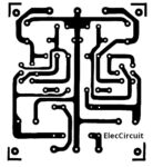
PCB Layout of Dual DC Regulator 15V using 2SC1061 and 2SA761
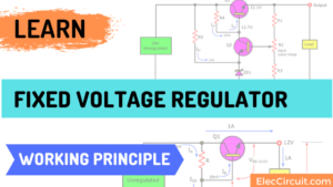
Simple 15 volts dual power supply circuit diagram
This is a very old circuit. It has 3 output voltage terminal are +15V, GND, -15V at maximum 500mA.
Also, it is ideal for a pre-audio amplifier circuit like the integrated circuit LM7815 and LM7915. But sometimes we cannot them but we can use this classic circuit.
It includes transistors and 15V Zener Diodes as simple Dual DC regulator. Though it is ancient, it may be good for you.
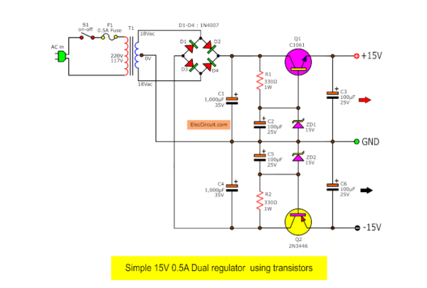
Simple 15 volt dual power supply circuit diagram
How circuit works
When 117VAC (250VAC) is fed to the power cord, the neon-lamp L1 light up, and transformer T1 changes 117VAC to about 28VAC. The bridge D1 to D4 rectifies the AC in DC, next to both capacitors C1, C4 acts as a filter for a smooth DCV. Now we have +33V CT -33V DC unregulated.
Then, the electrical current flow to both 330 ohms series resistor for limit current to the Zener Diodes ZD1, ZD2. They keep the voltage constant across the base of transistors at 15V cause Q1, Q2 works increase high current to the output.
Parts you will need
Q1: BD139 or 2N3053, 60V 1.5A NPN transistor = 1 pcs.
Q2: BD140 or 2N4037, 60V 1.5A PNP transistor = 1pcs.
D1-D4: 1N4007, 1A 1000V Silicon Diodes = 4 pcs.
ZD1, ZD2: 15V 1W Zener Diodes
C1, C4: 1,000uF 35V, Electrolytic Capacitors = 2 pcs.
C2, C3, C5, C6: 100uF 25V, Electrolytic Capacitors = 4 pcs.
R1, R2: 330Ω 1W Resistors tolorances 5% = 2 pcs.
T1: Transformer 15V CT 15V or 18V CT 18V 1A to 1A = 1 pcs.
and more…
Download This
All full-size images of this post are in this Ebook: Elec Circuit vol. 2 below. Please support me. 🙂
Cannot get parts
If you cannot find both transistors.
You may use Q1-2N4053 = 2N4037 or BD140 pair with
Q2-2N3446 = 2N3053, BD139 instead of them.
You can buy easy and the price is inexpensive. Hope friends have fun the Dual linear regulator +15V -15V Circuit.
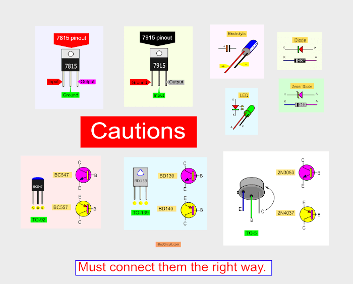
Cautions
I believe you have the ability And learned electronics enough. I just review it for you, most components are polarized. They must be connected into a circuit in the proper direction. Otherwise, the circuit will not work or be damaged.
Look at these polarized components.
IC-7815, 7915, transistors, Zener diode, Diodes, electrolytic capacitors, and more.
Especially 7915, we don’t use it often. can be confusing.
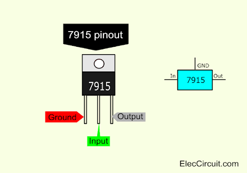
7915 Pinout
I hope you have fun with this Dual DC Regulator 15V using transistors. If you think that This circuit is not good enough. For your work. It is hard to find equipment. You do not have it now. These circuits may be viewed below. It may be appropriate for you.
Dual power supply 15V using LM317,LM337
GET UPDATE VIA EMAIL
I always try to make Electronics Learning Easy.
Related Posts

I love electronics. I have been learning about them through creating simple electronic circuits or small projects. And now I am also having my children do the same. Nevertheless, I hope you found the experiences we shared on this site useful and fulfilling.
hello, thanks for this..
can i replace the 12-0-12 with 15-0-15 but still getting +15v and -15v as output?
if yes, what other components will need to replace? thanks
thank you. Can you provide the complete discription of the circuit and why you use the 6 capacitor. And can you tell me the working of ic properly. And what is the meaning of the 7815 and 7915 ic. why 7815 is used for positive polarity. Thanks in advance.
Thanks, I’ll use this schematic! 🙂
BTW, same question as eboy, may I just use 7812/7912 to get 12-0-12 with the same circuit?
very good
Hi mansoor.
Thanks for your feedback.
Superb blog you have here but I was curious if you knew of any discussion boards
that cover the same topics discussed in this article?
I’d really love to be a part of group where I can
get suggestions from other experienced individuals that share the same interest.
If you have any suggestions, please let me know. Kudos!
ola gostaria de um controlador de 15v porem com uma maior amperes, posso usar mais de um trasistor para almentar a amperagem. pressiso ligar o controlador em um painel solar de 24v 8A para carregar uma bateria de 12v 40A
Is 12-0-12 is enough forvthis 15v dual power supply?
Hi, everybody.
I am sorry error of transformer’s output voltage.
We should use 15V ct 15V or 18V ct 18V.
Thanks for all comment.
7915 connections input pin 2,,,ground pin 1,,,output pin 3,,,,7815 connections pin 1 input…pin 2 ground and pin 3 output Thanks For a Handy Dandy Little Circuit!!!
@supul…Please Refrain from Cursing On This Site,,In other words BE NICE!! If You Would Check Your Data Sheets You Would Have Rectified The Problem!!! @ admin..Keep up the Great work,,,This Site is MR.OHM Approved!!!
Thanks Momename For All Your Hard Work… KEEP UP THE GOOD WORK,,,Thanks For EVERYTHING!!!!PS**** This Is a FUN SITE,,,YOWSA!!!!
can you please reveal the design details of the capacitors used?
Perhaps Supul ought to check the connections….
I do hope he relaises the pin out on the 7915 is not the same as the 7815!!!!!
Should his amplifier be a split rail he would see ‘smoke’ should he not build the PSU right.
WHY didn’t he check the supply was working correctly before connecting to ANYTHING???
…..
As for the 2,200uF capacitors, the rule of thumb you need 2,200uF per amp, so for 2 amps say one would need a 4,700uF unit.
Any transformer less than 15V will not provide enough voltage for the regulators…. consider the diode rectifier drop and the voltage drop across the regulators as well as transformer loading.
Any transformer greater than about 18V will cause excessive heat in the regulators.
When running high power, certainly above about 0.5A it would be advisable to use a finned heat sink on the regulators or at least bolted to a sheet of aluminium – remember the 7915 will need to be isolated from earth because the tab/ middle pin is the -Ve output.
DO REMEMBER the connections of the 7915 IS different to the 7815…. and the above supply does work!!!
I made the circuit, but i am getting +/- 22 output. What did i do wrong?
I have a Behringer RX 1602 mixer that is motorboating intermittantly. The LED lights blink off and on when this happens and the speakers pop very loudly. It has a 7915 and 7815 ICs. Could it be one of these or one of the filter caps? There are 4 caps. The values are hidden from view. Two are larger than the other two and there are 4 disc caps. Can you please advise me ASAP. THANK YOU.
What would cause loud “motorboating” in the speakers ? If a capacitor, which ones most likely OR could it be the 7915 or 7815 IC ? Thank you !
meu compresor de audio behriger modelo mdx4600 queimou otransformado otransisto ic7815 e ic7915 são afetado
Using 7815 and 7915 I am not getting perfectly 15 volt or-15 volt ….
My circuit output is 16.43 and – 17.32 ….
So what will change require in my circuit????
Hi Ambu,
Thanks for your feedback.
Yes, you can use this circuit for DC dual +/- 22 output.
Hi Ravi,
Thanks for your feedback.
You can use low drop out voltage regulator ICs.
for example: https://www.eleccircuit.com/portable-power-pack-using-lm1086-for-mobile-phones/
but it hard to buy general shop.
Hi
Schematic of dual 15v power supply with transistors 2sc1061 and bc548 totaly incorrect
everyone should adjust resistors 2.2k value !!!!!!!!this blog for kids only
author is baby in electronics …..
Hey.
Ive build this circuit and the L7815 is running really hot in seconds, anyone might know why?
Cheers
How do i get 2A current instead of 1A on the output side. What are the changes to be made to the circuit ?
Hi anjali,
Thanks for your question. Please look at:https://www.eleccircuit.com/boosting-regulator-current-for-ic-78xx-by-mj2955/ or https://www.eleccircuit.com/10a-dc-supply-fix-regulated-by-ic-78xx-and-mj15004/
Hi dre,
Thanks for your feedback. You may use load over 0.5A.or short circuit.
Hi I am building the Coin Battery Circuit that you have on your system for a 1.2v Button Battery Charger,
My question is, is ther any way I can alter the circuit so that I can charge 4 LR44 Rechargeable batteries in series,
Hope you can help
Regards
Brian
Dual 15V Power supply Schematic, 1A with IC-7815, IC-7915
R1 – 2700 ohm .25 Watt resister.
The LED will have about 2v across it, leaving 28V across the resistor.
P = E^2/R = (28*28)/2700 = .29
That resistor will burn up pretty quickly
Hi Al Zoot,
Yes, You are correct. There is the voltage across it about 48V.
The power is P = IxV = 0.02 x 48 = 0.9W. It is 1 watts resistor.
Thanks for your helping.
PS. I hope you Come to visit me again.
500mA, 15V dual regulator
Can i use transformer 18V, 5A?
Hi,
Yes, you can do it.
0.5 mA dual regulator
Can i use transformers 18v?
Hi
You can use this circuit. IC 7815,7915. It Can be used up to 1A.
Can I replace the 15-0-15 power with two 15v DC power supply adaptors and how?
Hi friend,
How are you? I am happy that you like this circuit.
You mean You have a DC 15V (+ 15V and GND) power supply.
But you want to use it with a load that needs + 15V, GND, -15V.
I got it correct right?
It is going to be very difficult. If so
If your load requires a very low current you may use this circuit.
It is an easy idea.
https://www.eleccircuit.com/lm2577-5v-to-12v-dc-converter-step-up-voltage-regulator/
https://www.eleccircuit.com/dc-converter-5-volt-to-12-volts-or-high-volt-than-12-volts/
https://www.eleccircuit.com/the-many-dc-to-dc-converters-using-ic-555/#Simple_Dual_Power_supply_from_single_supply
If I misunderstand your needs Please forgive me.
Hope you will come back to share your experience. I will wait.
Hi, thank you for replying to my question.
Yes I want to use ordinary power supply that has out put of +15v and -15v to supply this amplifier that require dual power supply of +15v, and -15V and GND, the reason is that the present transformer price is too high to buy and build power supply but obtaining power supply complete is fraction of the price.
The three schematic you send me with thanks I am not sure if they can supply dual voltage to the amplifier.
I have tried the following, I removed the transformer and rectifier and connect the ordinary commercial adapter that has +15v and -15v to the + of capacitor C5,c7 and -ve of capacitor c6,c8 then used the GND from the four capacitors to the GND of the amplifier, the amplifier works fine, I measured the GND voltage and found it 7.5v DC, is that will replace the need for the dual power supply needed for the amplifier?
Hi, again.
Hmm, You should the small current transformer 15V CT 15V. It is cheaper than high current.
It is easier than a DC converter or switching mode power supply above links.
Yes, you should use a 15V Dual power supply regulator for the preamplifier.
Hi Apichet,
Thank you very much for replying to my question.
Its the third link you send is close to answer my question,I want to use Dual_Power_supply_from_single_supply, how can I achieve this? I found details on the third link but its not clear I cant find the input voltage and the out put dual voltage?
Hi again,
These circuits are ideas of circuits.
They are not best for audio systems. But you can try it.
I believe you can learn it works.
Have a good day.
Thanks again.
Hello Sir,I have a transformer without secondary voltage details.W.R to service manual made a hand sketch for your reference.I need voltage at 1&2 and 4&5 with amps.I request pl be check and help me to find ratings for replacement Transformer.
Hello S.Kathiravan,
Thanks for your visit. Your way of thinking is interesting. Because there are many 2-terminal transformers. But this solution You may have to try a half-wave rectifier. It is easy and cheap. However, it may have other ideas to do it. Please share this idea.
Thanks again.