This is a 0-30V Variable Power Supply circuit. With conveniently adjustable output voltage from 0V to 30V, at 3A current, and overload protection.
Also, it is a high-efficiency regulator by using a UA723 IC-regulator, and a TIP3055 power transistor. So, it is a great pick for a small laboratory DC Power Supply usage at an inexpensive cost.
Overall, I recommended this power supply to anyone who needs 3A output with a wide range of voltage for normal uses.
For anyone looking for a 0-12V and 0-24V variable power supply circuit, this circuit will also work as well. Because of its high current, use normal parts and a new circuit design.
Feature of 0-30V Variable Power Supply
- Modern design—I used to show you the old circuit using LM723. But it only powers a current at just 2A and it uses a 2N3055 power transistor. Also, it is more difficult to make. Instead, this current circuit use TIP3055. It is slimmer so easier to install on a heatsink.
- Output voltage—adjustable output voltage : 0-30VDC
- Maximum Current —all range of output voltage it can power current up to 3A
- Inexpensive—if you compare it with old circuits, this circuit is cheaper.
- Part needed —you should use a 12-0-12V 4A transformer for full current up to 3A.
How does it work
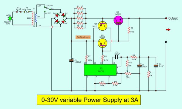
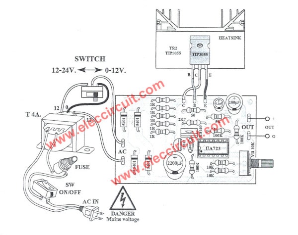
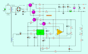
As Figure 1 circuit diagram. The order of operation is interesting.
Oops! Here is too difficult. Look at…
0-30v variable power supply. or
Here is step by step a process.
- Reduce AC voltage
The AC main to a transformer reduces the AC high to AC low voltage. See below, how to set the voltage as you want. - Rectifier AC to DC
Low AC voltage flows through the bridge diodes(D1 through D4) set. They rectify AC to DC pulse voltage. - Unregulated DCV
C1 is a filter capacitor to the pulsating voltage into a steady direct current (DC). Before, send it to… - DC regulator circuit
The voltage comes to IC1 and some parts. They keep the output voltage is constant. Even the load will draw a current too many, the voltage is still stable.
If you want to read more detail about LM723 circuits you can visit. Datasheet!
But the current out of pin 11 of IC1 is very weak. They need increasing current. - Increase current
Two transistors Q1 and Q2 are connected in Darlington mode, so a lot of gains. - Adjustable voltage
You rotate VR1 to change the output voltage between 0V and 30V. - Special voltage selector
Adjusting VR1 at low voltage is difficult. Such as 0-12V, 0-10V, and more.
But this is special, you can select a range of voltage in 2 steps, low and high, with SWITCH in a circuit.
Low: 0-12V and High: 0-30V. If you cannot imagine, see below!
Overload Protection
Detect overload
Sometimes it is too much current that the transistor and other parts tolerate it.
You look at parallel resistors(R1 to R5) that are reduced to 0.2 ohms to detect overload current.
If the current exceeds 3A. The voltage across these resistors more than 0.6V.
Also, The voltage at the base-emitter of TR3 is 0.6V, making it works.
Between its collector-emitter likes, a switch closed.
It also connects with the base-emitter of Q1. It makes Q1 reduce working, the current is lower.
Then, Q2–power transistor stops working too. Thus, the output is low current, this circuit is safe.
Let’s build them
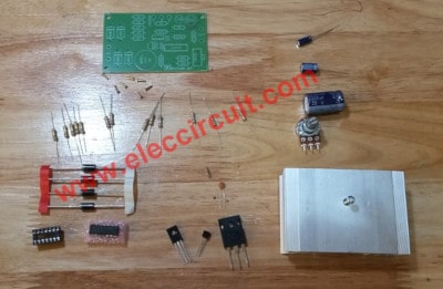
First of all, get the electronics components.
Parts you will needs
We may buy them at electronics stores near you or online to get parts.
IC1: uA723-HIGH PRECISION VOLTAGE REGULATOR
Q1: BD140, 80V 1.5A PNP Transistor
Q2: TIP3055, 60V 15A, high-Speed Switching Silicon transistor
Q3: CS9012, 40V 0.5A PNP Bipolar Transistors
D1-D4: 1N5401, 100V 3A Rectifier Diodes
Electrolytic capacitors
C1: 4700uF 50V
C3: 100uF 50V
Ceramic Capacitors
C2: 680pF 50V
C4: 0.1uF 50V
0.5W 5% Resistors
R1-R5: 1 ohms
R6: 50 ohms
R7, R9, R12, R13: 100K,
R8: 2.7K,
R10: 10K,
R11: 5K,
VR1: 5K, Potentiometer
Others
T1:12V-CT-12V, 4A transformer
Heatsink, PCB, Wires, and more…
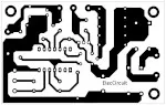
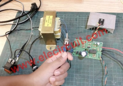
Here is the PCB layout.
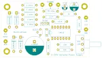
And this is the components layout
Note:
Here are the KITS that I bought from a local store. If you want to save time, it can be ordered through Amazon.
Where buy electronics components
Assembly
Then, Assemble the components on PCB.
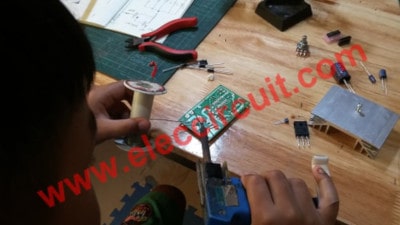
It starts with the lowest parts first, to be beautiful. Easy assembly To start with, followed by a diode, resistor, and respectively height and so on.
As the image below soldering lowest electronic components.
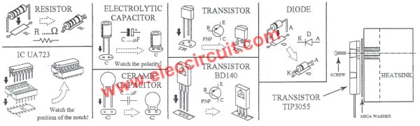
Be careful!
Some components have polarity like electrolytic capacitors, diodes, transistors, etc.
They require correct placing. If they are the wrong polarity. They will get destroyed from reverse voltage.
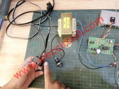
The components layout and wiring of this 0-30v Variable Power Supply project.
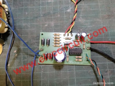
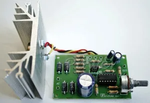
We assembled all parts completely on PCB.
This project uses AC power so we must be careful about high voltage.
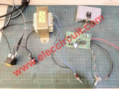
Finally, we have made this project so successful.
Applications
The connecting “12” and “0” will be through a selector switch.
For 2 selector;
- Use voltage 0-12V at “0”
- Use voltage output 0-30V at “12,12” the voltage minimum is 0.3V to maximum is 33 volts.
This way makes the transistor, not overheat.
The output we should connect a 3A fuse in series before to use.
Testing
We test this project. As the video step by step.
- Apply the AC power then turn on power switch ON.
- Select Switch to 0-12V Before then Rotate the knob VR1 fully the left.
- Measure voltage at the output point, then rotate the VR1 slowly to right, the output voltage starts is 0.3V or 300mV to 16VDC maximum.
- Toggle switch to “12-24V” then measure the voltage again 330mV to 32 volts.
- Setting the output is 12V, then Apply a 12V 50W as the load.
- Measure the current output when load 12V is 3A maximum.
- Temperature measurement of transistor operation.
How to solve circuit not works
If you made this project but it did not work. No worry. It is not a problem. It is a process of electronic learning. You should have fun solving it.
Here are some basic guidelines for you.
First
No load, No power to this circuit. And Check and Check again with slowly. Surely, something is wrong.
Second
If you check all is correct. You try to power to the circuit again. Then, measure the voltage at.
- TP A (Test point)—It should read voltage about 33VDC. If it is not like this.
You should check the unregulated voltage again. Which include a transformer, bridge diodes, and C1. - TP B—Also voltmeter should read about 33VDC. But it is zero or lower voltage. Show that parallel resistor, R1-R5 are broken.
Third
Check the circuit again. even pins of IC1.
Equivalent Transistors
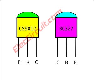
CS9012
If you Cannot find a CS9012 transistor you may use an equivalent transistor is BC327 PNP transistor. But Different pinout positions between the Emitter and collector.
CS9012 datasheet : http://www.mouser.com/ds/2/149/SS9012-117759.pdf
Ice = 500mA max, Vce = 40max
BC327 Datasheet : http://www.mouser.com/ds/2/149/BC327-30422.pdf
Ice = 800mA, Vce = 40Vmax
Download This
All full-size images and PDFs of this post are in this Ebook below. Please support me. 🙂
If you want better circuits, look here!
0-50V 3A Variable DC Power Supply
GET UPDATE VIA EMAIL
I always try to make Electronics Learning Easy.
Related Posts

I love electronics. I have been learning about them through creating simple electronic circuits or small projects. And now I am also having my children do the same. Nevertheless, I hope you found the experiences we shared on this site useful and fulfilling.
plz upload pcb for this supply
Where I buy this pcb board
Do you have the whole power supply as a kit with PC BOARD?
What A Handy Dandy Little piece Of Test Gear To Have Around Your Test Lab!! Thanks MOMENAME
Can I get this circuit kit with in 2 -3 days !?
hi..how to design this circuit..how to calculate the value ..will you tell me how to design this power circuit
Hello !!!
His name is Tien, Vietnam .We himself as he was the Student attending Electronics industry, I have enjoyed watching your product, I want to embark on the implementation of this product, You can ask yourself Printed circuit Board (PCB) of you. If possible I would like to thank you very much 🙂
Another idea for a bench or lab supply, that is even less expensive, is to re-use the power supply unit (PSU) from an old computer. The following link gives detailed instructions for converting and reusing the PSU from a disused or old computer
fadstoobsessions.com/Electronics-Projects/DIY-Tools/ATX-PSU-Conversion.php
The transformer in the parts list is 12-0-12V, could you explain how the circuit can produce up to 30V DC Supply, thanks
Hi vlady,
Thanks for your answer. Please check voltage across C-4700uF is 33V-35V DC. and check circuit again slowly. It is worked!
Would you please share your PCB for this project? Thank you! From Philippines…
hi. tks for all but could you share your PCB for this nice and usefull projet?
hi. Thank for all but could you share your PCB for this nice and usefull projet?
Hi sir I always checked your projects and I really love it can you give me the PDF file or pcb layout ang parts list plssss
I want to make this
[email protected]
Hi, any equivalent for CS9012 as nowhere it’s available here in India.
Is it okey to use diode(4007)
You may use a diode 1N5402 better in 3A 100V.
Hello sir i need a voltage schemes regulate 0-30 + –
Hello, I’m new to the site, I wanted to groped with all of you for the simplicity and precision with which you do these things for nothing simple for a novice like me. You are the most interesting site I’ve ever found on electronics, and I’ve visited many, thank you for what you do.
Is it okay to replace the transformer to 12V 3A or 14V 4A
Hi, Lander Ignacio
You are welcome.
Yes, you can use 14V CT 14V or 28V output transformer.
It is 39V DC at C1. And the output voltage regulator will rise up to 35V approx.
If you have any results. Please back to here again.
Thanks.
Yep!!!!!
How to modify this for higher current .i.e. 5A instead of 3A?
Hi,
You may try this: https://www.eleccircuit.com/0-50v-3a-variable-dc-power-supply/#Can_increase_current_up_to_5A
Use 2N3055 or TIP3055 instead.
I am sure because I not do test it.
Have a good day.
Does it have anything if I use a simple 28V transformer?
Hi George
If you use 28VAC. It is 28Vx1.414 = 39V at output maximum voltage is approx 36V to 37V.
I want to add a display for the variable voltage and one for the current. I need you to help me with how to set it up.
Hi Donatus,
I’m not sure about your question. But this may be of benefit to you.
https://www.eleccircuit.com/lm317-power-supply/#Add_LED_Voltmeter_display
Hi, could you tell me how to add a short circuit protection?
We soldered the circuit with all recommended components, cs9012 blasted, burned up after switching on, what might be the cause?
Hello Manvee,
Thank you for making this project.
I am sorry to hear that. Something wrong CS9012 maybe high current or reverse polarity.
Please recheck again. I believe you can do it, cool down step by step.
Hai. I would like to have a variable power supply. This supply has to be varied based on an voltage input in the range 0-10V or 0-5V. This external voltage input comes from a PLC analog output. So for example the Variable power supply is in range of 0 -30. If plc sends 1V then the supply should give out 3V and so on. Thanks in advance
Hello, Suresh
Thanks for your visit. How are you?
Your question is interesting. I want to learn how to use a PLC. It has an output voltage of 0-5V, but the current is very low, right?
How would you like to implement this circuit? It is a power supply
I am interested in this If you will explain to me as well, it’s very good.
Have a good day.
Apichet
how many watts are the resistors
Hello, Victor nanshir,
Thanks for interesting in this circuit. You can use 0.5watts of resistors.
Thank you for your enthusiasm in the electronic business. For the 0-30V Variable Power Supply at 3A project, where can I obtain the printed PC board or just the image so that I can have it made where I live.? Thank you
Hello Robert,
Thanks for interesting in this circuit.
I am sorry. I do not know where to buy the PCB of this circuit.
However, You may build it in the Perforated PCB. It is quite easy and quick than making a true PCB.
It work good, thanks
Hello Tom,
Thanks for your feedback.
Hello! I’m a beginner in electronics and I saw your design. I have two question, is it possible for me to increase the current capacity of this circuit up to 30 amps and also add a potentiometer to control current? By the way, I would like to commend your efforts in creating posts like this one which can be easily understood by the readers despite having basic knowledge in electronics. Thank you in advance!
Hello Carlos,
Thanks for your visit to my site. Your opinion is very interesting.
Let me to opinion to you.
– The 30 Amps is very high current. But it is always possible.
You need to change the main components for the 30A rating. For example transformer, D1 to D4 diodes are 50A bridge diode and C1 are 47,000uF. Because it needs high current.
But I’m not sure about the details of other devices like the Power transistors. You may need to parallel several of them to make them able to amplify more current.
and for adjusting the current.
I am frustrated that cannot explain it to you in full. Because I never made it.
In the future, you will experiment with it.
I want to make this unit. Therefore, I want to contact you. Please send your contact number.
Hello Mervin Dahanayake,
I send all detail about this circuit to your email. I hope you can build this circuit.
Have a good day.
Resistor R6 value is 500 ohms on schematic and only 50 ohms on the PCB.
Which is correct?
I aplogise. on closer examination I see is 50 ohms on both. so no problem.
Although ..I must say it seems awful low. Nearly a short circuit?
It’s okay dear friend, R6 is 50 ohms. It is a load of Q1 (PNP transistor). Q1 is the pre-drive for Q2 (power transistor) to work. E of Q1 is connected to the highest positive voltage (C1) and R6 is connected to the output or E of Q3. The voltage across this point is quite low. Your point is very interesting. But I can’t explain it simply now. I prefer to explain with pictures.
However, this circuit I have tried to build and it works well, not a short circuit.
Have a great weekend.
hello Apichet,
Nice to read your project articles. Do you have a negative regulator circuit with adjustable currentl imit using LM723 and external PNP boost transistor ? Also can you tell me how to add current limit, overload and short circuit protection to LM317 with external current boosting transistor.Thanks
Hello ramana,
We thank you for your inquiry.
Because my dad (Apichet) is quite busy these days. He took on many responsibilities. According to the nature of a dad who is busy with everything. I so would like to inform you that Your problem is very interesting. I am also interested in power supply circuits. Because I saw my dad build it in many circuits. LM317 is also very useful. We use it very often. We’ll try it again according to your idea. But not sure When will it be finished. I apologize for not being able to respond to you quickly, hope you can understand. 🙂
10 – out !!!!!
11 , 12 – v in + !!!!
7 – in – !!!
Hi,
It is correct as datasheet. But I made it runs well.
Thanks