If you want a Dual Variable power supply circuit that covers the most appliances. This circuit may be what you are looking for. With the following features.
1. On signal mode—can supply DC voltage of 0V to 60V.
2. On Dual rail mode—Can provide DC dual variable on positive, negative and ground, are +/- 0-30 volts.
3. Can supply current out the maximum of about 1.5 A.
4. Use the most popular IC are LM317T and LM337. So, do not worry about finding the devices, and it is certainly easy.
Before construction, we should learn the properties of important devices, regulator IC.
Choosing Regulator IC
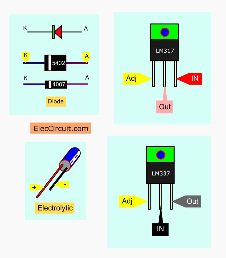
The regulator IC is used to regulates DC voltage. Which in this circuit, we use an IC number of LM317T for the positive voltage and the LM337 circuit for the negative voltage. Both ICs have the same features. Just only it is the different polarity. Thus, describes specific number LM317T only.
The LM317T is the adjustable regulator IC, can adjust the output voltage of 1.25V to 37V. There are 3 pins and the body is the same as the regulated IC, 7805.
But it can provide to 1.5 A and gets input voltage of 3V to 40V. It is easy to apply and these features have advantages more than regular IC 78xx series a lot.
In addition, Internal the LM317 has full protection, the short-circuit protection, input over voltage protection, overload protection. Another interesting feature is the elimination of the ripple.
The output voltage (Vo) determined from the formula.
Vo =1.25{1+(R2/R1)}
The R1 is the resistance constant from 120 Ohms to 240 Ohms. We can adjust resistor-R2 from a minimum value (0 ohms) to the value as we want. If R2 is 0 ohms minimum output the voltage of about 1.25V.
Related: LM317 Calculator
Making LM317 start at 0 volts
In electronic circuits require a constant voltage. The output voltage of LM317T may not need to reduce to 0V. However, in the experiments, we may be necessary to start the voltage at 0V.
It has this weakness. The minimum output voltage across between Adj and the ground is 1.25V.
But here is how you can make the output is 0V, it is easy to do that.
By creating a reference voltage is lower than the zero 1.25V. It is -1.25V. Then, take this voltage to the Adj. So you can adjust the output voltage to 0V.
The negative voltage regulated IC, LM337T is similar to LM317. If the Adj connects to the ground, get lowest output voltage is -1.25V.
Which if you want to adjust the output voltage is 0V. You need to connect Adj of LM337 with the positive reference voltage, +1.25V.
How Dual variable circuit works
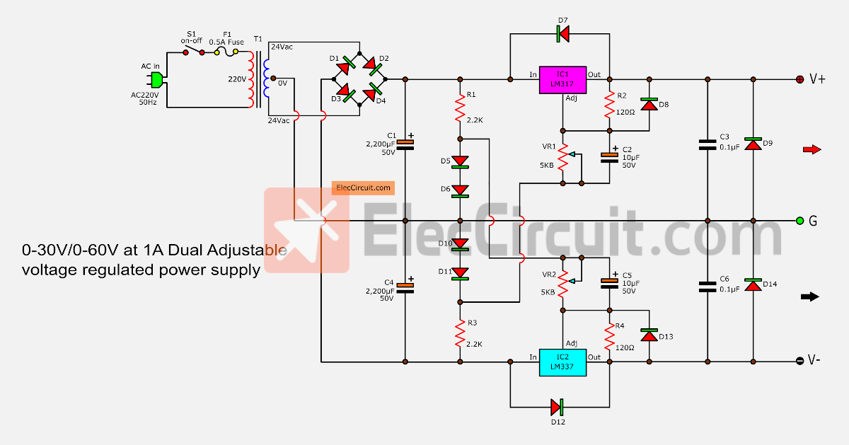
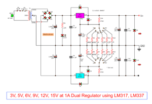
In figure 1 is this complete circuit. The Diodes D1-D4 are rectifier ACV from 24 volts of the transformer into DCV of about 33V, in both positive and negative voltage.
The capacitor C1 and C4 are a voltage filter from the bridge diodes to smooth.
The R1, D5, and D6 are made the reference voltage of +1.25 volts to the LM337T to adjust the voltage to start at 0V.
The R3, D10, and D11 make voltage -1.25V to LM317T. It can also adjust the beginning voltage is 0V.
The D7, D8, and D12, D13 protects voltage backward voltage from the output. Which may make IC Which may cause damage to the IC.
The C2 and C5 are connected to reduce the noise signal from adjustable the potentiometer (VR1, VR2) and makes the voltage at the output to smooth up.
Judicially built and tested before applications
This project has a few amounts of devices. We can assemble onto the perforated board. You need to check and check the circuit for error. When you are sure all the wires and components are installed correctly
After examining successfully assemble the devices. Then, try to apply AC power. If everything is not wrong. Hold the DC voltmeter to measure the positive output. And then Rotate VR1, you can read the voltage from 0-30 volt.
If everything is correct, then move the lead of the meter to measure the negative. And then adjust the VR2, you can read voltage from 0-30 volts.
Everything is ready for applications. However, if the malfunction, disconnect the transformer. Then looking for the error.
Building Dual Variable power supply circuit
This project is not used many components so can assemble on the universal PCB board. But can make a Single-sided PCB layout as Figure 2. And see the wiring and various components layout can view the example in Figure 3.
But be careful the polarity of the electrolytic capacitors and Diodes and both IC1-LM317, IC2-LM337 correctly and hold proper the heatsink.
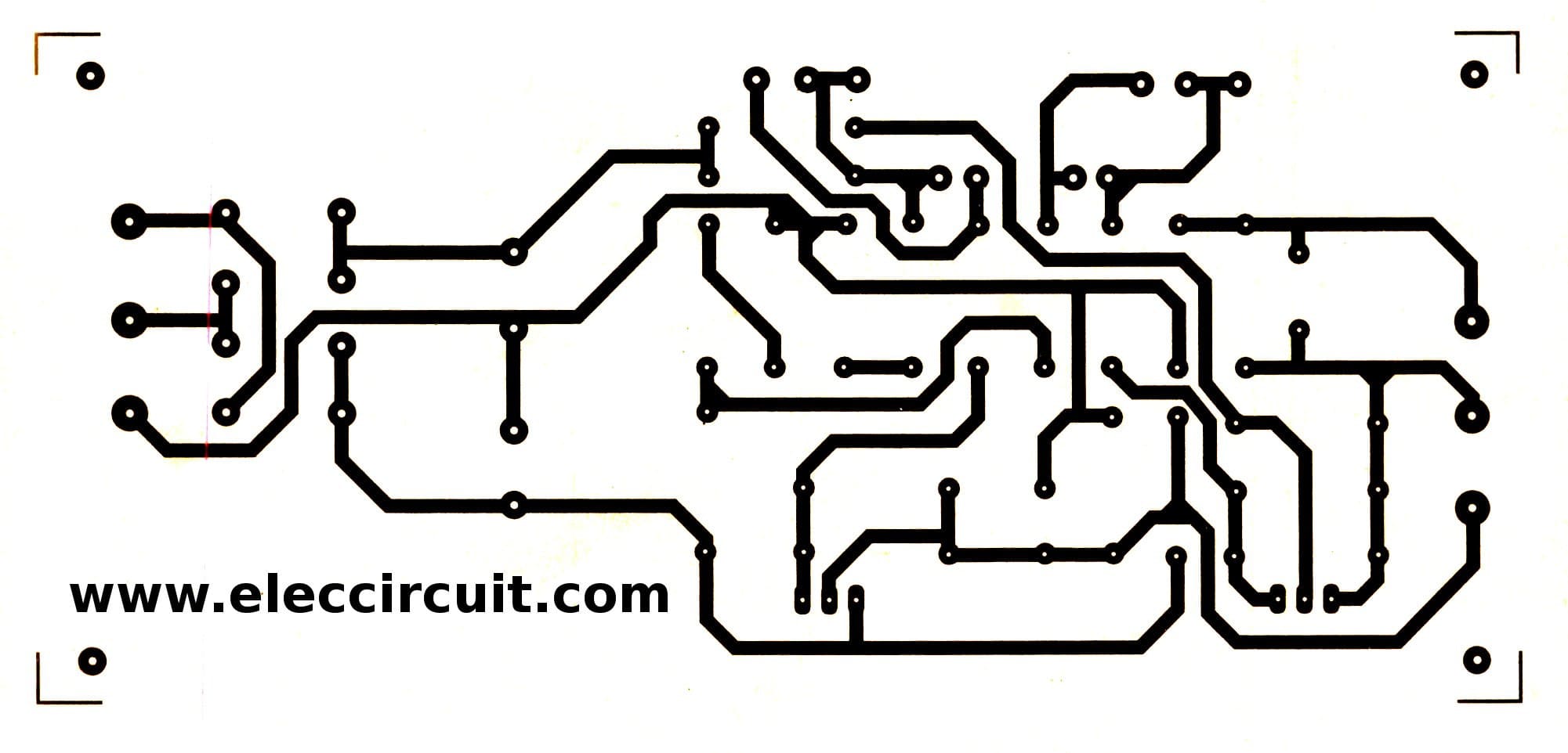
Figure 2 The Single-sided PCB layout
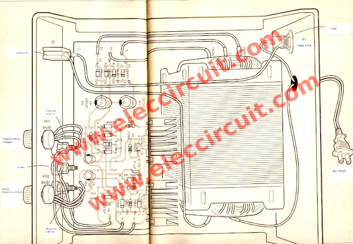
Figure 3 The components layout of this projects
Note:
The LM317T is positive voltage regulator ICs that low watts because are the plastic case or TO-220 model.
The LM317K is higher watts because of the metal case TO-3 model.
The LM337T is negative voltage regulator ICs in TO-220 model
See: LM317K pinout
The Shopping Lists
Here is an electronic components list that you can find anywhere.
- IC1: LM317, Variable Positive DC regulator IC
- IC2: LM337, Variable Negative DC Regulator IC
- T1: 24V CT 24V, 2A transformer
- R1, R2: 2.2K 2W Resistors
- C1,C4: 2,200uF 35V Electrolytic capacitors
- C2, C5: 10uF 35V Electrolytic Capacitors
- C3,C6: 0.1uF 50V Ceramic Capacitors
- D1-D14: 1N4007, 1A 50V Diodes
- VR1, VR2: 5K(B) Potentiometer
- S1: ON-OFF Switch
- F1: 0.5A Fuse
Be careful polarity component
Some components have the polarity. For example, the electrolytic capacitors, diodes, LM317, LM337, etc. If you incorrect them. Your circuit does not work. Event them damage.
Also Dual variable power supply
This circuit may not suitable for you. You may like these circuit below.
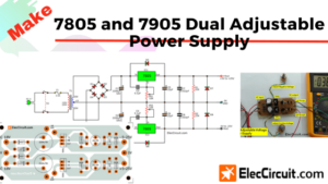
- Dual adjustable Power Supply using 7805 and 7905
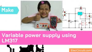
- LM317 Power supply circuit —My first Variable DC Power Supply 1.2V to 30V It’s easy and cheap as possible.
- LM317 Linear power supply Regulator selector 1.5V,3V,4.5V,5V,6V,9V 1.5A It’s easy to selects voltage output.
- Best DC power supply 3Amp to adjust 1.2V-20V & 3V-6V-9V-12V High current for all circuit easy to use.
- Dual power supply 3V,5V,6V,9V,12,15V with LM317,LM337There positve and negative voltage output for all circuit easy to use.
GET UPDATE VIA EMAIL
I always try to make Electronics Learning Easy.
Related Posts

I love electronics. I have been learning about them through creating simple electronic circuits or small projects. And now I am also having my children do the same. Nevertheless, I hope you found the experiences we shared on this site useful and fulfilling.
Your drawing was completely wrong ! How could both output marked as V+ ??
D14 anode side output should be V-
Did this silly mistake nobody checked it out before posted ?
can somebody check the diagram if its correct,.. please, i was supposed to make this p.s but i just had read that comment… please somebody check..
Hi,Lee26 Loo
Ohh.. I must apologize for the error.
You are very kind that please tell me.
I modified successfully.
I tried to assemble this circuit but nothing happends ,I dont know why , all my connections are correct..
can you give me some idea admin?
There is no out put comming out..
i tried this one but no output comming out
did anyone tried this circuit???
I’m sorry.
All circuits, I gathered from the book, which I have not tried this before, it may be a errors.
D14 to be correct, Pin V-successfully modified.
is circuit revised?>>>
Just finished a version of this. added 4 power transistors for extra current. It works great, but I think I need to add current limiting before i call it a done project. Thanks for the concept.
Can you reduce the output voltage to 25 V?
I want to construct 0 to 12volt dc power supply that can suplly up to 100Ampere. How can I achieve this task using all the components listed above?
I will be expecting your repply.
I want construct variable power supply in which both the current and voltage can be varied.Please How is this possible
I have build the 0-60v variable power supply above but only the positive part is varying while the negative remains constant.I don’t know what is wrong please I need urgent assistance.
Hi do you know how to make 0-18 volts 2amp power supply?
hey i should mirror the pcb layout then print or what?? please reply
I think for get more current (more than 1A) u can use parellel circuits given above.But you have to make sure about R1,R2 values and all parellal values should be varied in the same time
Is the 1.5 amp per side, 3 amps total? or 1.5 amps total?
Pl ,give me the correst circuit.
Can we increase the value of R1 and R3 to decrease the current
Hi Jawaaz,
Thanks for your feedback.
Yes, you can.
Hi
Is there a difference between lm317t and lm317h? The multisim that l am currently using, do only have lm317h.
Hi Angel,
Thanks for your feedback.
The LM317T is positive voltage regulator ICs that low watts because is plastic case or TO-220 model.
The LM317K is higher watts because metal case. TO-3 model.
The LM337T is negative voltage regulator ICs in TO-220 model.
Awesome design. I have been looking to make a 60 volt power supply for a few days now. Any tips on a household outlet that uses 120V?
can i request a circuit diagram of an automatic variable voltage power supply from 0 to 6 volts 30 amp with an input of 12 volts dc. The power goes up automatically once the switch is turn on in just about 15 to 20 seconds. it must be an escalating power. Thank you so much if you could help me with this!
Hi Remigio T. Flores,
Thanks your feedback.
I am cannot surely help you.
In mysites have many idea:
https://www.eleccircuit.com/0-50v-3a-variable-dc-power-supply/
You may use transistors for increase current.
same this : https://www.eleccircuit.com/high-current-12v-30a25a20a15a-ham-radio-power-supply/
and use simple timer as this: https://www.eleccircuit.com/timer-set-for-30-minutes/
Hi,
I used LM317 (normal).
Work fine!!! 0 to 30V 1.3 Amp.
Great
Hi,
I based my circuit on your design and I used a 5k six-pin potentiometer to adjust the voltage however I want but my problem is that the value between ground and negative is different from the value I get between ground and positive. I designed it so that they should have the same value. What do you think my error is?
Its not a lot of difference but still, I want them to have the same value.
Do you need me to send you a copy of my design?
I would be really grateful if you could somehow respond to my question.
Thank you.
The problem occurs because the sections of your double potentiometer have got various resistances, there is a resistance toleration of probably 20%. But you can easily overcome this by replacing R2 or R4 with a 200Ω trimpot and changing its resistance in order to make the output voltages equal. First, you have to set, say, 100Ω on the trimpot before you turn the circuit on. Then you have to set maximum resistances of potentiometer’s sections. After that, you can rotate the trimpot to make both voltages equal.
Yes, I know there is too late to help you, but I hope that my reply will help someone else.
Hi Patryk,
I am very impressed with you for helping. Your advice is very valuable. Useful for everyone, of course.
Hey Can you tell me is this circuit worked for anyone? I have tried twice but my voltage is remaining constant and it is not regulating.
I want to build the circuit and i want to put a LED as indicator, where can i put the Led?
im getting confused on where exactly do i need to put the two ic’s i might connect it the other way around, can someone help me identify which ic goes on what side. thaaaaankyou!
I’ve tried building this twice and it worked like a charm! I’ve tried messing with the pot to get a 35V output on both positive and negative!
I had similar idea looking for a diy 0-60V 5A output power supply.
The simplicity of your schematic has helped me a lot and the 4 diodes ladder to achieve 0 V is brilliant.
The only defect of the schematic is to have to use 2 potentiometers to adjust V+ and V+ to obtain (by add) the desired Vout.
I put you this eBay live item of a special stereo 5K potentiometer with which turning 1 single axis you can simetrically vary V+ and V- at the same time:
141509282505
Hello Ric! 1 Pt 2b noted here is that your proposal of using ‘ganged’ pot of 5k is theoretically noteworthy. However these pots are not precision or hi tech and are primarily made for the less forgiving Analogue applications like audio amp etc. There may be significant diff in the carbon track ohmage in the two of them which could lead to puzzling tracking errors in your final opt V. This is for your information. TY…
sir,
I’m apply this circuit veritable volte 0-60v 30Ampere fixed current, so what I do????
plz teal me.
you give me 1 circuit a lot of good for me
Do you test it???.
I did the circuit as per your diagram. Positive supply perfectly varied, I mean perfectly working but negative side not varied properly as positive side. Negative side going down in variation up to -24 volt to -25 volt. It is not going down to 0volt or -1.25 volt. Please recheck your diagram and give me solution.
If I want to adjust current with this circuit then what I will Do?? ???
Hullo, I would like a circuit diagram of your LM317T/LM337T power supply but I find I am unable to print out your very helpful project. Can you send me a copy of it please? Mike.
How is this going to put out 60 Volts?
Hello, Tom
Thanks a lot for your feedback. I am trying to rewrite the post. I hope my English grow up.
R1, R3 is overheating, that means power consumption.
Hello Silveriser,
Thanks a lot for your making this circuit.
Yes, both resistors are hot. We may modify this circuit new.
If you try this circuit again. Can improve this circuit again Please let me know. Thanks in advance.
Which Transformer we have to use ?? Rating of Transformer??
Hello Raju,
Thanks for your question. This transformer is 2A 24V CT 24V Secondary.
I built this and the regulators blew many times. Other designers said it’s likely because lm317 limits are near 30v and in regulated 24v exceeds it
Hello Frontier9,
Thanks for your visit. You are correct. It is really in use.
I love it for a long time, very cheap and easy to use.
What IC can use for 30V regulated? Please tell me.
Thanks a lot.
Apichet
Chris
I have something for you here I hope you can start something Chris
Hello Chris,
Thanks for your visit and your ideas. It is great and useful for everyone.
Thanks again.
Apichet
Due to large input & output voltage difference multiplied by high current of 1.5 A, there will be higher power dissipation than specified 20 watts on datasheet, this power supply can’t be used for 1.5 Ampere loads on lower output voltage
Hi, my dear friend,
Thanks for sharing. LM317 and LM337 are great ICs. But they are not perfect. What can we do to improve them?
God Bless you always be happy
Works even with 2x 32vdc printer power supply just get rid of the bridge rectifier, replace the 2200uF with non-polar 0.1uF capacitors. The center tap is replaced where the 2 power supplies connect together in series.