Circuits such as a preamplifier tone control use OP-AMPs that require constant 12V, -12V, and ground; in other words, a 12V dual power supply circuit. There are many ways to get these three terminals; using L7812 and L7912 voltage regulator ICs is one of them. These chips are easy to use, inexpensive, and of quite high quality.
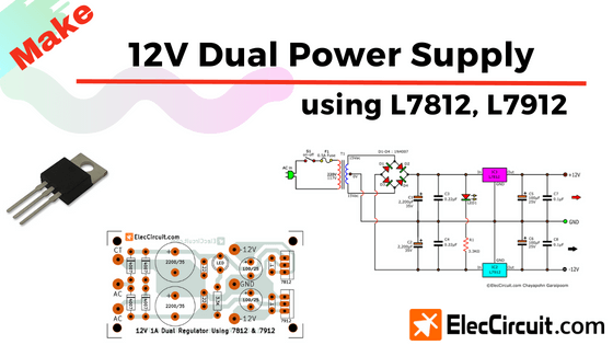
So in this article, we are going to see two different ways to make a 12V dual power supply circuit using L7812 and L7912. The first circuit is the simpler one, but it will only use a half-wave diode rectifier. However, the second circuit will produce a better quality voltage because of its use of a full-wave bridge rectifier. We would recommend the second circuit over the first one because it can supply a much higher current.
Read more 12v power supply circuit using 7812
Simple 12V Dual Power Supply Circuit using 7812 and 7912
Consider this circuit when your load only requires a current of no more than 100mA (0.1A). Or, if you only have a pair of 1N4007 diodes available and are in a hurry for a simple dual power supply, this circuit would also work.
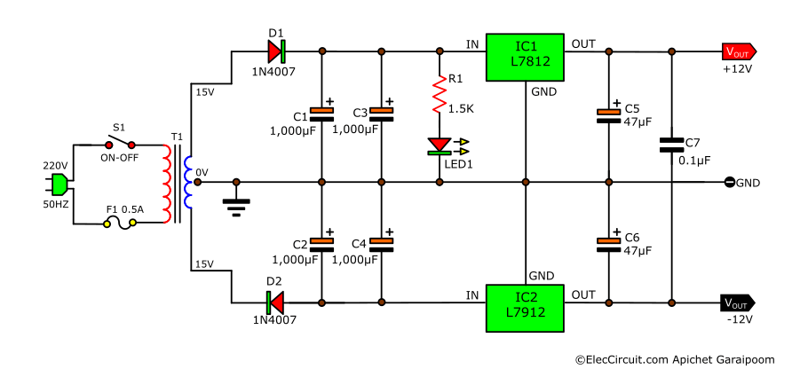
The first part of this circuit consists of an unregulated power supply, which includes S1, F1, T1, D1, D2, C1, C2, C3, and C4. Since this circuit only uses two rectifier diodes in a half-wave rectifier form, we should also add two more filter capacitors, C3 and C4, in addition to C1 and C2, to reduce ripple voltages. These capacitors work together to smooth out the DC pulse from a half-wave rectifier to a stable DC voltage.
C5 and C6 are additional filter capacitors to reduce ripple voltages. C7 cleans transient voltage at the output. LED1 is just a power indicator for this circuit, and R1 is its current-limiting resistor.
This circuit uses a main to 15V CT 15V (30V) 0.25A transformer. Converting AC to DC voltage brings the total voltage up from 30VAC to about 42VDC; half of that—or 21VDC each—goes into both the L7812 and L7912. Then, the regulator ICs maintain a constant +12V and -12V at their respective outputs.
Because of the low amount of current that goes through them (100mA), both L7812 and L7912 may not need heatsinks to function.
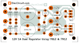
High-Current 12V Dual Power Supply Circuit using 7812 and 7912
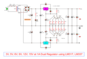
This circuit is suitable for those seeking a 12V dual power supply circuit that can supply 500mA or more. This circuit would also produce higher-quality voltage than the previous circuit. In terms of design, this circuit is very similar to the previous one, with only a few components replaced and added.
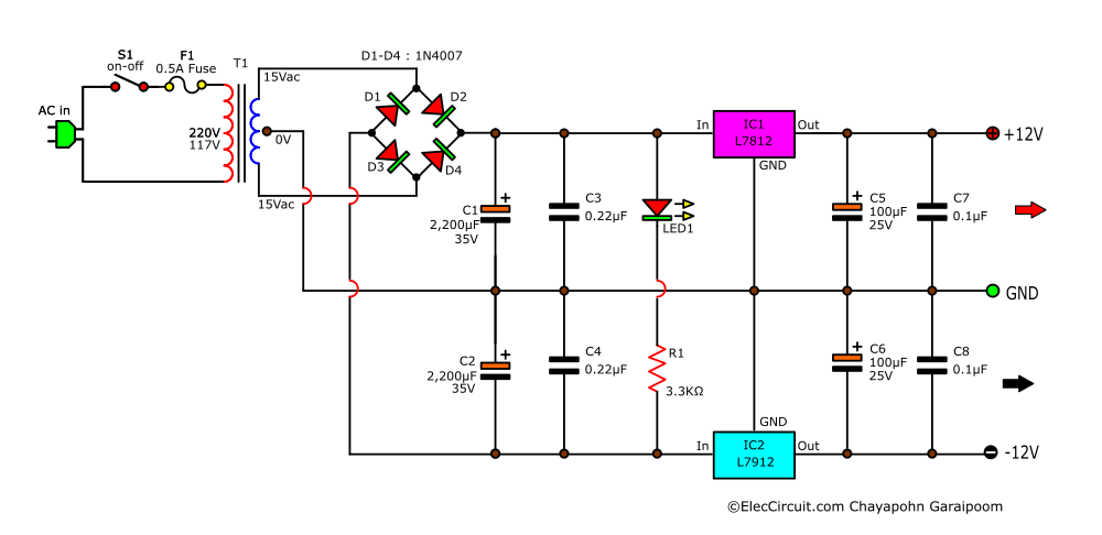
First, the current of the transformer increases to 1A, as this circuit will have a higher output current. Next, a half-wave rectifier from before is now replaced with a full-wave rectifier consisting of four 1N4007 diodes.
As for C3, C4, C7, and C8 filter capacitors, they clean the transient voltage at the input and output, respectively. C5 and C6 filter out ripple voltage at the output of the circuit. Lastly, LED1 and R1(limiting current resistor) indicate if the circuit is functioning or not.
Additionally, the L7812 and L7912 regulator ICs may warm up a little because of the higher current flowing through this circuit. Although it would not be dangerous, we recommend installing heatsinks to extend their lifespan.
Parts list
- IC1: L7812 Positive Voltage Regulator
- IC2: L7912 Negative Voltage Regulator
- D1-D4: 1N4007, 1000V 1A Diodes
- C1,C2: 2,200uF 35V Electrolytic Capacitors
- C3, C4: 0.22uF 50V Ceramic Capacitors
- C5, C6: 100uF 25V Electrolytic Capacitors
- C7, C8: 0.1uF 50V Ceramic Capacitors
- LED1: Normal LED
- R1: 3.3K 0.5W Resistor
- T1: 220V or 117V to 15V CT 15V 1A Transformer
- S1: ON-OFF Power Switch
- F1: 0.5A Fuse
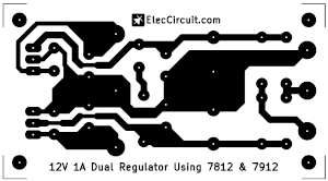
Building this Circuit
Since this circuit does not have that many components, you can assemble it on a perforated board. However, you could also design a proper PCB for it, similar to the component layout and copper layout shown below.
Other external circuit ideas:
+/-12V DUAL POWER SUPPLY
Troubleshooting
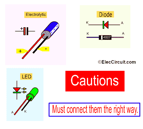
In the case that the circuit does not turn on or it does not function as expected, it might be because of placing a component in its wrong polarity. Some components have a designated polarity that we have to keep an eye on, because reversing their polarity can cause all sorts of problems to the circuit.
Here are a few components that we have seen missed in the past.
Electrolytic capacitor: in the wrong polarity, it will bulge or straight up burst.
Diode: It will cause irregular voltages if placed in the opposite direction.
LED: It would not turn on.
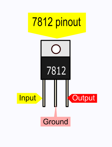
L7812 and L7912 pinouts
Since we have been using many 78xx series ICs, such as 7805 voltage regulator, we already have a pretty clear idea of the 7812’s pinout. The 7812 has the same pinout as the 7805 and other ICs in the series.
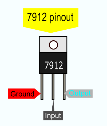
7912 Pinout
However, the 7912 chip does not share the same pinout with the 7812. Its input and ground pins are reversed when compared to the 7812. Connect the 7912 with the wrong polarity, and it will not function and will heat up greatly.
Be careful 7912 pinouts is not the same 7812. It is difference pins input and ground. I switched it. My 7912 is too hot. Please look at it again.
Conclusion
We think that these circuits are very useful in that they can supply power to OP-AMP circuits reasonably well. They are also easy to build; you can pick one of the two based on the resources and time you have.
Also, these DC powers can also be turned into a 12V dual power supply circuit.

I love electronics. I have been learning about them through creating simple electronic circuits or small projects. And now I am also having my children do the same. Nevertheless, I hope you found the experiences we shared on this site useful and fulfilling.

Appreciable!!!
But u dint explained the design nicely…How u have calucalated the value for capacitor?? And working of circuit also..??
Dear Team,
I have 2V/500Ah cells (24nos) in a place for running a equipment and for auto generation of DG I am keeping 12V/120A battery, I want to avoid this DG battery (12v/120Ah) need circuit for this.
Govind
dear sir
one project develop my self is 3.2 volt series led light ( power led used). 29 nos.
and transformer less power supply for 225 k/4oo polyester capacitor circuit developed.
but led is does not continuous working.
its only 480 hrs. runing and led circuit problem
so please suggest to me. any idia for circuit
thanks
hello sir, can you make a powerbank to smart phone with rechargeble powerbank.. please tell me…
20-9-20;Raviichettu Center;Chinaravuru Park Rd
Hi Jagadeesh Prasad.
Thanks for your feedback.
I have a 24 0 24 dc to 12 0 12 converter circuit
Hi,
You can use DC +24V 0 -24V to +12V 0 -12V Because see 7812 and 7912 in data sheet. We can use for 25VDC max.
T1: 220V or 117V to 15VA CT 15V transformer ………….How many use ampere transformers?
Hello Abdur Rahman,
Thanks for your visit to my site.
I am sorry. I forgot. It is a 1A transformer.
Thanks for your question, so good.
Have a good day.
Nice
Thanks😊
otimo artigo, descriçao e analize perfeito.