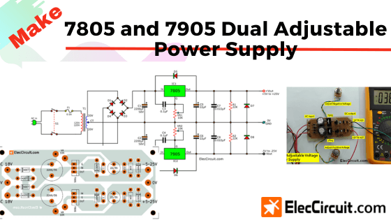
Let’s build a cheap adjustable dual power supply circuit that uses a 7805 and a 7905 linear regulator IC as the main components. This circuit is also a great way to understand the basics of OP-AMP circuits.
It can supply a voltage ranging from +5V to +25V and -5V to -25V, which means that it can supply both positive and negative power. Both rails are also operated separately by different optentiometers, hence the ‘dual’ in the name.
Why should we build this circuit?
Suppose that we are testing an OP-AMP IC, such as uA741, LF351, OT071, et cetera. Usually, you would just use two 9V batteries. Simple enough, right?
But the energy in the batteries is limited, so you will have to buy a new pair of them at some point. And there’s a high chance that your new batteries might not have the exact same electrical properties as the old pair, which may introduce unnecessary variables to your testing
Circuit ideas that you can get useful
More Voltage
Other reasons are that sometimes the experiment might require higher voltage levels, such as +10V GND -10V or +18V GND -18V, which is difficult, if not impossible, to produce with batteries.
More Current
Furthermore, the battery can only power a current of 150mAh, whereas this circuit can power up to 500mA currents at a stable voltage level of 12V. However, when using a load that consumes a current of about 350mA, the voltage level will drop to a constant 11.9V.
It can supply a maximum current of 1A, but at that point, the voltage will decrease by about 15%. This means that if we set the output voltage to 10V and then connect a load that draws about 1A of current, the actual output voltage will drop to 8.5V.
You could see it better, right? In any case, OP-AMP ICs typically do not consume that much power.
Another thing we like about this circuit is that it has low noise, which is similar to general batteries. As we have observed during our OP-AMP experiment using it, there was next to no interference in the high-frequency circuit.
Why chose 7805 and 7905
Nowadays, switching regulator ICs, or other types of regulator ICs, have higher efficiency. But the 7805 chip has remained popular over the last 30 years. It’s always our first choice when we need a 5V stable-voltage power supply for a small circuit because it’s simple to use and inexpensive.
From my experience, if used with a load that requires a current of less than 300mA, it is highly stable and durable. In some circuits, we ran it 24 hours a day for more than 5 years and it still hasn’t broken down. But you must also install an adequate heat sink for it.
Designing Circuits And Estimating Components Easily
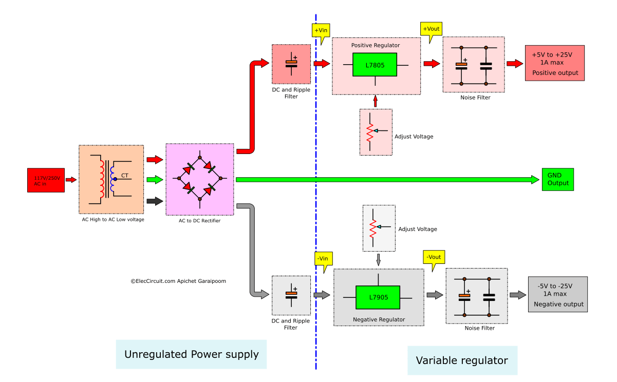
Based on our rough requirements, we can create a simple block diagram, as shown below.
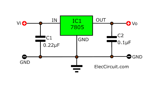
Simplest L7805&L7905 Circuit
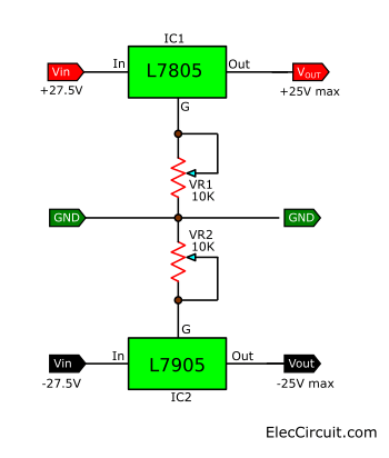
First, we know that we use 7805 and 7905 regulator ICs and two potentiometers(VR1, VR2) for adjusting an output voltage as a simple variable power supply circuit.
Recommended: 7805 variable voltage regulator circuit
Let’s find the Vin for both of them. Normally, these regulator ICs require the input voltage to be 2.5V higher than the output’s. So, if we were to set the maximum output voltage to 25V, we would get:
Vin = Vout + 2.5 = 27.5V.
Unregulated Power supply
So, we will be using this 28V DC unregulated power supply circuit as shown below.
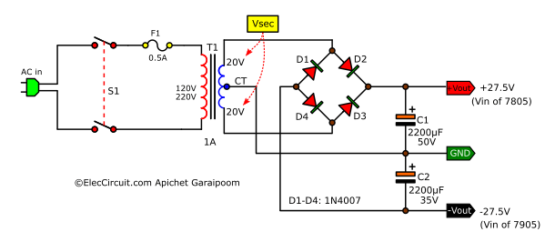
The AC voltage flows into the circuit through the S1 ON/OFF switch and passes F1 to protect against overload current. Next, the AC voltage flows to the primary coil of the transformer (T1) to be converted to a lower AC voltage.
The Transformer
It converts a higher AC to a lower voltage.
Since we want both the positive and negative output, we would also need the GND from our transformer. This means that we are going to use a transformer with a center tap on the secondary coil and a bridge rectifier, as shown in the circuit above.
We also want a maximum current output of 1A, so we need to use at least a 1A transformer with a CT 20V secondary coil. 20V obtained from the calculation:
Vsec = Vin ÷ 1.4
The Vin is an input voltage of 7805/7905 regulators.
Vin = 27.5V
Vsec = 27.5V ÷ 1.4 = 19.64V
Therefore, it is recommended to use a 20V secondary coil, or you may use an 18V transformer like in our prototype circuit. But the actual voltage we measured was 18.89V, causing the Vin to drop to 26.46V, which is still close enough to what we need.
The Rectifier
It rectifies AC to DC voltage.
In this case, we will use four 1N4007 (1A 1000V) diodes connected together in a bridge form.
Finding the Value of Filter Capacitors
Next, we can calculate the capacitance of the C1 and the C2. Both act as a DC filter, giving us a smooth DC voltage. Since both are equal, we only need to calculate the C1’s using a simple formula as follows:
IL is load current, which is 1A max.
F is a DC pulse’s frequency, which is twice that of AC. For example, in EU = 50Hz or US = 60Hz, in our case we use 100Hz (DC pulse).
Vrp is the ripple voltage rate. A normal power supply circuit usually has a ripple voltage of approximately 10% of DCV. In this case, our DCV is 27.5V. So, Vrp is 2.75V.
Substitute the values in the formula:
C1 = 1 ÷ (2 × 100 × 2.75)
C1 = 1,818.18µFWe will be using 2,200µF 35V for both C1 and C2 instead.
Noise Filter
For this circuit, we need to keep the noise as low as possible. Let’s say we are testing a preamplifier circuit using an OP-AMP IC such as uA741. But instead, we hear noise mixed in with the music we are listening to. The noise can occur from a variety of points, but it typically travels through the power supply.
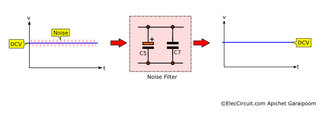
The noise signal has a relatively high frequency and is combined with a DC voltage. It may appear insignificant, but after passing through a high-gain amplifier circuit, it will become much more noticeable.
The solution is to add decoupling capacitors. The 7805/7905 datasheet requires the addition of output capacitors (C5 and C6), for which we chose a 22uF 50V electrolytic capacitor for each.
However, their high-frequency response is poor, so this may not be sufficient. So we should also add C7 and the opposing C8. The noise will see C7 as a very low-resistance resistor, so it will flow through it to the GND, and the DC voltage is immediately cleaner.
But how much capacitance should the C7 have? There is a fairly simple formula for calculating this:
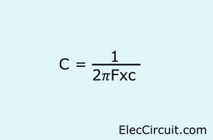
F is the frequency value of the noise signal; the unit is Hz.
XC is the resistance of a capacitor that only affects the AC. It has units of ohms, usually set at 1Ω for easier calculation.
But the problem is that we don’t know the exact value of F, or frequency. We do not have an accurate enough frequency measurement tool. So, we use the method of guessing the F first, then work our way backward, starting from 10Mhz (10,000,000Hz).
Substituting the C7 = 1÷(2×𝜋×10,000,000×1)
C7 = 0.0159µF
We will use 0.022µF instead.
Now let’s rearrange the formula, isolating the XC on one side, and find its value.
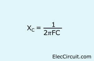
XC = 1÷(2×𝜋×10MHz×0.022µF)
XC = 0.72Ω
But if that still doesn’t work, we will try increasing the capacitance another 10 times, which is 0.22µF, which will have a lower frequency response of 1MHz.
The Protection Diodes
Although 7805/7905 ICs already have quite a good protection system, a reverse polarity voltage can still damage them. So we should also include protective diodes (D5 to D8).
The D7 and D8 diodes act as output polarity reversal protection against external reverse voltage into ICs, such as that from large external capacitors, which can be damaging.
The D5 and D6 diodes act as reverse bias protection. If the output suddenly has a higher voltage than the input, it may damage the regulator ICs. The addition of these diodes thus bypasses this voltage instead.
Read more: The Diode Protection for 78xx series.
Now, we put all the components together, turning it into a complete 7805 and 7905 dual adjustable power supply circuit, as shown in the diagram below.
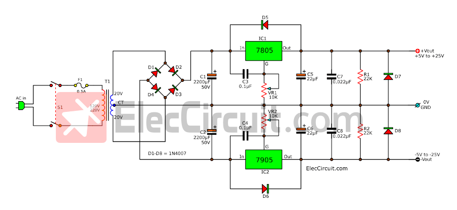
Additionally, we added C3 and C4 to reduce noise, which means that high-frequency noises will pass around both ICs.
And we also add R1 and R2 as bleeder resistors, which help discharge the current from C5 and C6 to improve the efficiency of the circuit.
How to build
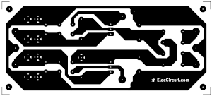
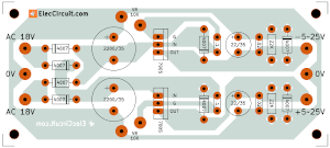
This project consists of quite a few electronic components and details. I think that we can solder all components onto the perforated PCB.
However, some of our friends wanted to assemble it on the PCB. So my son designed a PCB for him, and it works pretty well. We assembled it quite nicely, as shown in the image below.
Part lists
T1: 18V-20V CT @1A primary transformer, Quantity:1.
IC1: L7805, 5V 1A Regulator , Quantity:1.
D1 to D8: 1N4007, 1A 1,000V – Silicon Diodes, Quantity:8.
R1, R2: 22K 0.25W , Quantity:2.
VR1, VR2: 10K(B) Potentiometer, Quantity:2.
C1 to C2: 2,200µF 50V Electrolytic capacitor, Quantity:2
C5, C6: 22µF 35V Electrolytic capacitor, Quantity:2
C3,C4: 0.1µF 50V Ceramic or Mylar capacitor, Quantity:2
C7,C8: 0.022µF 50V Ceramic or Mylar capacitor, Quantity:2
During our testing of the circuit, we made a mistake while connecting the transformer’s secondary coil, causing the voltage to rise and the capacitor to overheat, nearly damaging the IC.
If Vin is higher than 30V DC, it may cause these ICs to malfunction and become damaged. Therefore, we must exercise caution when connecting electrical components with clearly defined electrical polarities, such as diodes, electrolytic capacitors, ICs, etc.
In particular, the 7905 chip has different leg arrangements than the L7805. You should be especially cautious.
If you want to use this circuit to supply current up to 1A, you should increase the size of the heatsink because it cannot dissipate heat quickly enough, resulting in less current.
In the prototype, we needed no more than 300mA of operating current, so a small heatsink would suffice.
Testing
We tested this circuit by turning VR1 (positive voltage) and VR2 (negative voltage) completely counterclockwise and measuring the voltage, which should be at +5V and -5V, respectively.
Then, turn clockwise continuously. It will read the voltage increase according to our voltage adjustment. Until it reaches all the way, it will read the highest voltage, which is around +24.5V and -24.5V.
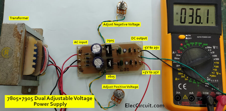
Next, adjust VR1 and VR2 until you get +18V and -18V, which gives a total voltage of 36V, as we want. Then, connect two loads (two 100Ω 1W resistors), and it will have the same voltage level. Changed or decreased only slightly. And L7805 and L7905 had a slight temperature increase. It shows that it can supply a current of approximately no less than 180 mA.
And, when adjusting the voltage to +12V and -12V and changing the load to 47Ω 1W resistors, the voltage level dropped to +11.3V and -11.3V. It is considered that this circuit works well enough.
Conclusion
This simple circuit works pretty well, exactly as we need it, and is economical too. We can use equipment that we already have (or can easily find) to create. Additionally, there are other dual-adjustable power supply circuits that can be used with the OP-AMP circuits listed below.
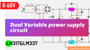
- 0-60V Dual power supply using LM317, LM337
- +15V CT -15V Dual Regulator circuits
- 12V Dual Power supply using 7812 and 7912
GET UPDATE VIA EMAIL
I always try to make Electronics Learning Easy.
Related Posts

I love electronics. I have been learning about them through creating simple electronic circuits or small projects. And now I am also having my children do the same. Nevertheless, I hope you found the experiences we shared on this site useful and fulfilling.
are the two terminals(terminal A and B) of the VR1 and VR2 are shorted??
Thank you for your early reply
Hey., I’m just getting 5V-20VDC.., I can’t get the
5V-25VDC..
Hi. I had read this post. Based on the description, the input voltage is 15V DC. I want to create a -5V DC based on this circuit. But I only have 9V DC adaptor with 1A output current. will it produce me a -5V DC too?
if i used a center-tapped 12V 750mA transformer, what else should be replaced in the circuit so it would work just fine? thanks in advance.
Hi,Alvin.
Thanks for your feedback.
Yes short terminal of VR1,VR2.
And you can use 18V CT 18V transformer for output 5V to 20V.
Hi,
I need 30v regulated low amp supply. Can 78xx be pushed to 30 volts.
Thanks
There seems to be a problem with the design. I tried to build it as shown, but got very narrow range variable output.
*I discovered you need from 150 ohm to 2500 ohm resistor from ADJ leg to OUT leg for both + and -, then you get full range adjustment.
**Also recommended to use 20 turn pots for finer control of output.
Are the diodes D5 and D7 essencial for the correct functioning of the circuit?
what will happen if + positive supply terminal and – negative supply terminal shorted means what will happen.Any protection like short circuit protection is there or not?
Hello Apichet,
I’ve been clicking various links and have been unable to find a PCB layout, both copper and component side for a dual DC regulator such as the 5v to 25v one you have listed above.
I have some old Heathkits that use batteries to provide +v and -v to power them.
I’d like to build a few of these using some center tapped transformers and 78xx and 79xx voltage regulators.
I’d prefer professionally made through hole PCBs but if I have the layout I could make my own.
Can you please post a link or repair one of the links that are supposed to point to a pcb layout.
Thank You
Tom
Hi,
Thank you for visiting your website, this circuit is very interesting, I am also thinking of building this circuit.
My brother is currently designing the PCB for this circuit, I expect it will be completed soon, hope you are looking forward to it. Thanks again for the great idea, hope you will continue to follow us. 🙂
My dear friend Apichet,
Good Day
Nice of you to provide the power circuit.
after going through the PCB layout. Can you recommend a simple and easy to do for beginners to electronics joining you?
Thank you in advance.
Michael sim
Hello,
Thank you for your message. I am pleased that you are interested in electronics.
It is quite confusing for beginners.
https://www.eleccircuit.com/learn-electronics/#How_to_learn_electronics_for_Beginners
We are more interested in electronics as a hobby. I want you to start by building a small electronics project first. Because it would be easier. In the future we will present articles about simple electronics. Hope you will keep following. Thank you.
I truly appreciate this post. I have been looking everywhere for this! Thank goodness I found it on Bing. You’ve made my day! Thanks again
Hi,
Thanks for your feedback.